22
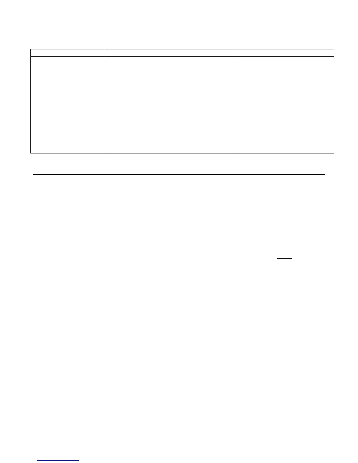
Table 3-1 Test Equipment Required for Troubleshooting
Type Purpose Recommend Model
GP-IB Controller Communicate with the load via the GP-IB Agilent 9825, Series 85, Series 200/300
Signature Analyzer Test most of the primary and secondary circuits Agilent 5005A/B
Digital Voltmeter Check various voltage levels Agilent 3455A or 3456A
Power Source Provide required input, bias GP-IB Board Agilent 6032A/6035A
Logic Probe Check data bus lines Agilent 545A
Oscilloscope Check waveforms and signal levels Agilent 1741A
Clip Leads Connect IC pins together AP Products No. LTC
Selftest Sequence and Error Messages
The turn-on selftest sequence consists of tests on both the primary (GP-IB) and secondary (Electronic Load) interface
circuits. If the load fails the selftest, the input will remain disabled and the display should indicate the type of failure. Table
3-2 lists all of the selftest error codes that can appear on the front panel display and provides the appropriate troubleshooting
information.
Primary Interface
The turn-on selftest sequence of the primary microprocessor consists of two parts:
1. The selftest is performed by the primary microprocessor (U203) and starts when the primary clear (
PCLR ) signal goes
false (High). First, the RAM, ROM, and the microprocessor's internal timer selftests are performed. If any of these tests
fail, the front panel display will probably remain blank. The failure can be detected by measuring a square wave on the
SA_GATE line at TP201-8 (see Figure 3-2). The type of failure is indicated as follows:
10Hz square wave--indicates a RAM failure.
100Hz square wave--indicates a ROM failure.
1KHz square wave--indicates an internal timer failure.
Square waves will not have a 50% duty cycle. It is also possible for a selftest failure to ''lock-up" the microprocessor and
cause a blank front panel display and no error square wave to appear on the SA_GATE line. If ''lock-up'' occurs, try to
isolate the problem by performing the Primary Interface S.A. Tests or by replacing U203.

 Loading...


