55
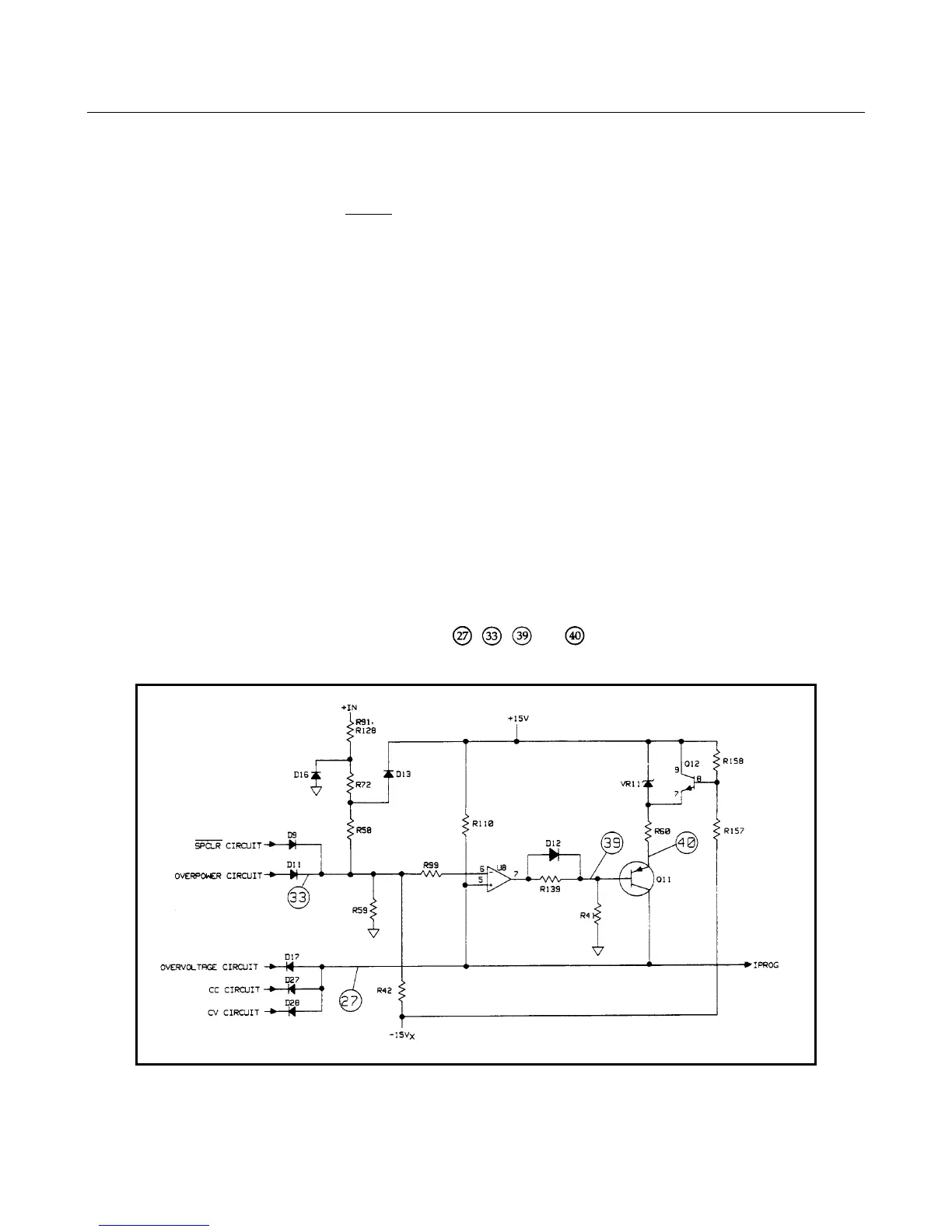
Overcurrent Circuit Troubleshooting (Figure 3-9)
This circuit limits the maximum current the load can sink for different input voltage and/or power conditions. The primary
components in this circuit are amplifier U8 and transistors Q11 and Q12.
At power on the secondary power clear (
SPCLR ) signal provides a High level via D9 to drive U8-7 Low turning Q11 on.
With Q11 turned on, IPROG goes High (less negative) and turns off the input power FETs (load will not sink current).
When the input voltage is about 6.3V (6060B); 40V (6063B), or lower, diode D6 is forward biased, causing voltage divider
R58, R72, R59, and R42 to hold U8-6 at approximately - 7V. This clamps the maximum input current capability between
45 and 66 amps (6060B): 10 and 11 amps (6063B)
As the input voltage increases from 6.3 to 65 volts (6060B); 40 to 260 volts (6063B), diode D16 is reversed biased and the
input voltage will appear across the voltage divider. This causes the voltage at U8-6 to decrease from - 7 volts to - 0.8 volts.
At an input of 65 volts (6060B); 260 volts (6063B), diode D13 turns on and holds U8-6 at - 0.8 volts and limits the
maximum input current capability to less than 11 amps (6060B); 2 amps (6063B).
When the input voltage reaches 75 volts (6060B); 287 volts (6063B), the OV circuit goes to -13V and pulls IPROG low
(more negative) via diode D17. The input power stages will now attempt to sink more current and decrease the input
voltage. If the combination of input voltage and current (power) is greater than the power stages can sink when OV
condition occurs, the overpower circuit (see next page) will override the OV circuit and limit the maximum current
capability of the load.
The -15VX bias voltage is a delayed bias derived from the normal -15V supply. When the load is first turned on, -15V is
not present and U8-6 is at common potential. This causes Q11 to conduct pulling IPROG high. Q12 is also on, connecting
Q11 to the + 15V bias. When -15VX comes on, Q12 turns off causing U8-6 to go more negative than U8-5. This turns off
Q11, allowing IPROG to go negative. VR11 supplies Q11 collector current once -15VX is available.
To troubleshoot the current limit circuit, check test points
, , and using the measurement conditions and
readings specified in Table 3-3.
Figure3-9. Overcurrent Circuit Troubleshooting

 Loading...


