30
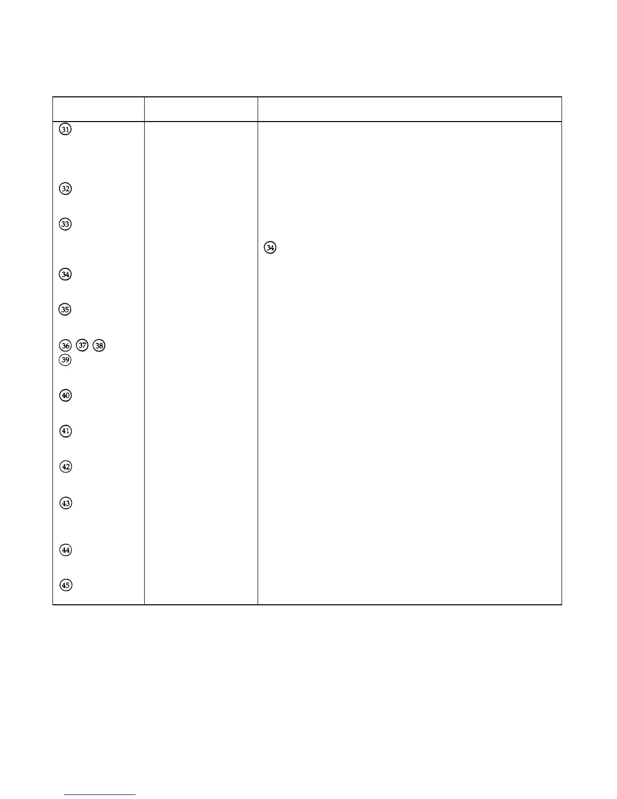
Table 3-3. Test Points (continued)
Test Point
Number
Signal Measurement and Conditions
U9-8
RNG Low level when the high current range or the middle resistance range is
programmed.
High level when the low current range, the low resistance range, or the
high resistance range is programmed.
U5-7
-VMON -0.167 X Input Voltage (6060B).
-0.0418 X Input Voltage (6063B).
D11 -cath
+ OP - 0.9V (full rated voltage input) to - 6V (zero volts input) when the OP
condition is false. Pulses when the OP condition is true. See test point
.
U7-1
-OP -14V when the OP condition is false. Pulses when the OP condition is
true. See Figure 3-10.
U12-17
-VMONA -0.167 X Input Voltage (6060B).
-0.0418 X Input Voltage (6063B).
NOT USED
D12 -cath
OC circuit control + 13V when OC condition false (normal). + 8V when OC condition is
true.
Q11-E
OC circuit control + 10V when OC condition is false (normal).
0V when unregulated or when OC condition is true.
D19-K
Input Power
Stage Turn on
+ 5V when turned on. 0V when turned off.
U1-1
Input Power
Stage 1
6.3V (approx.) with full rated input current.
-0.5V (approx.) with the input off.
Q1-1
Input Power
Stage 1
5.4V (approx.) with full rated input current.
4.0V (approx.) with 10% rated input current.
2.5V (approx.) at zero input current.
U14-1
Input Power
Stage 1
1.25V for at full input current.
U5-1
-IMON 10.02V at full input current.

 Loading...


