Rockwell Automation Publication 1734-UM013C-EN-P - August 2010 43
Install the Module Chapter 3
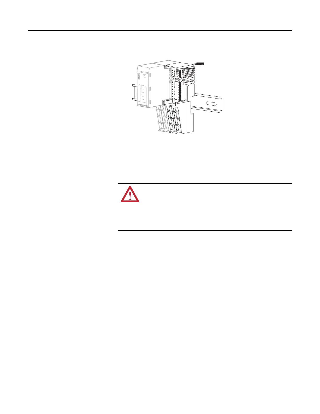
2. Slide the mounting base down, allowing the interlocking side pieces to
engage the adjacent module, power supply, or adapter.
3. Press firmly to seat the mounting base on the DIN rail until the mounting
base snaps into place.
Connect the Module to the
Mounting Base
Install the module before or after mounting base installation.
1. Using a screwdriver, rotate the keyswitches on the mounting base clockwise
until the number required for the type of module aligns with the notch in
the base.
Keep track of which mounting base gets installed on the left and right of
each module.
Slide the mounting base to
let the interlocking side
pieces engage the adjacent
module or adapter.
31868-M
WARNING: When you insert or remove the module while
backplane power is on, an electrical arc can occur. This could
cause an explosion in hazardous location installations. Be sure that
power is removed or the area is nonhazardous before proceeding.
Repeated electrical arcing causes excessive wear to contacts on
both the module and its mating connector. Worn contacts may
create electrical resistance that can affect module operation.
 Loading...


