Rockwell Automation Publication 1734-UM013C-EN-P - August 2010 93
Configure the Module in a GuardLogix Controller Chapter 6
Configure the
Output Configuration Tab
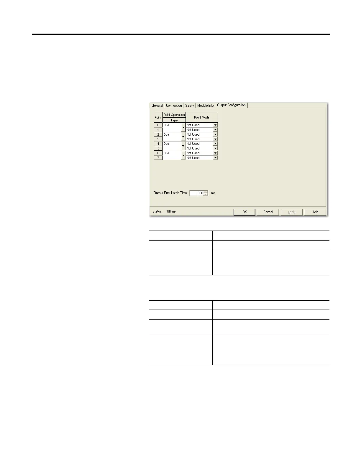
This section provides a procedure for configuring safety outputs by using the
information in this table and completing the entries referring to the figure.
Follow this procedure to complete the safety output configuration.
1. From the Module Properties dialog box, click the Output Configuration
tab.
2. Assign the Point Operation Type.
3. Assign the Point Mode.
Choose Description
Single
(1)
The output is treated as a single channel.
Dual (default) The POINT Guard I/O module treats the outputs as a pair. It
always sets them HI or LO as a matched pair. Safety logic
must set both of these outputs ON or OFF at the same time
or the module declares a channel fault.
(1) Does not apply to bipolar outputs.
Choose Description
Not Used The output is disabled.
Safety The output point is enabled, and it does not perform a
pulse test on the output.
Safety Pulse Test The output point is enabled and performs a pulse test on
the output. When the output is energized, the output
pulses LO briefly. The pulse test detects if 24V remains on
the output terminal during this LO pulse due to a short to
24V or if the output is shorted to another output terminal.
 Loading...


