EasyManuals Logo
Home>Allen-Bradley>Control Unit>1734-OB8S

Allen-Bradley 1734-OB8S Installation & User Manual

Allen-Bradley 1734-OB8S
156 pages
To Next Page IconTo Next Page
To Previous Page IconTo Previous Page
Page #53 background imageLoading...
Page #53 background image
Rockwell Automation Publication 1734-UM013C-EN-P - August 2010 53
Chapter
4
Wire the Module
Introduction
Read this chapter for information about wiring and safety categories.
Connection Details
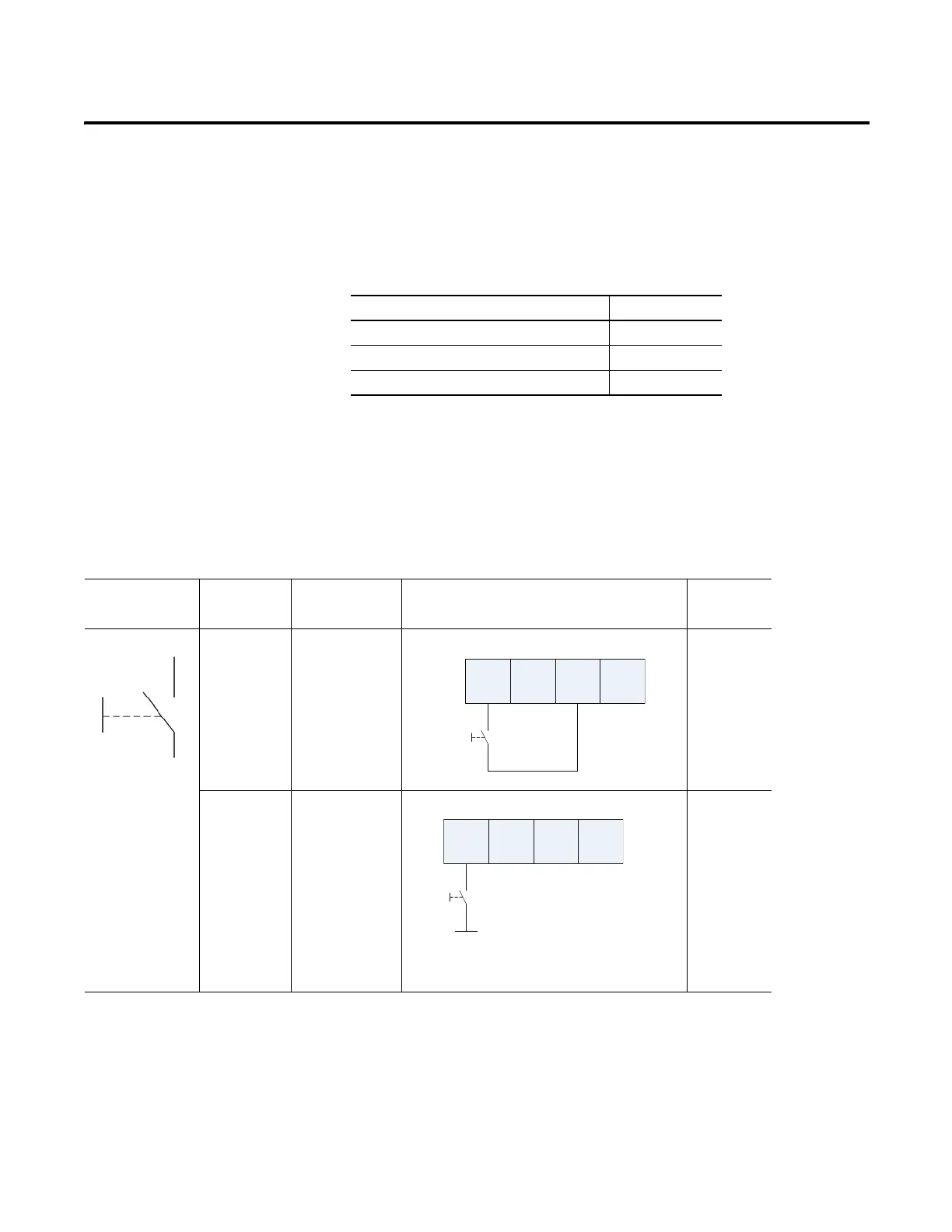
See the tables that show input device connection methods and their safety
categories.
Topic Page
Introduction 53
Connection Details 53
Examples of Wiring 55
Connected Device Test Pulse
from Test
Output
Connection Schematic Diagram Safety
Category
Push Button Yes Connect the push
button between I0
and T0. T0 must be
configured as test
pulse.
2
No Connect the push
button between 24V
DC and I0.
1
I0 I1 T0 T1
I0 I1 T0 T1
24V DC

Table of Contents

Other manuals for Allen-Bradley 1734-OB8S

Questions and Answers:

Question and Answer IconNeed help?

Do you have a question about the Allen-Bradley 1734-OB8S and is the answer not in the manual?

Allen-Bradley 1734-OB8S Specifications

General IconGeneral
BrandAllen-Bradley
Model1734-OB8S
CategoryControl Unit
LanguageEnglish

Related product manuals