120 Rockwell Automation Publication 1756-UM013B-EN-P - October 2019
Appendix C Application and Wiring Examples for Safety Modules
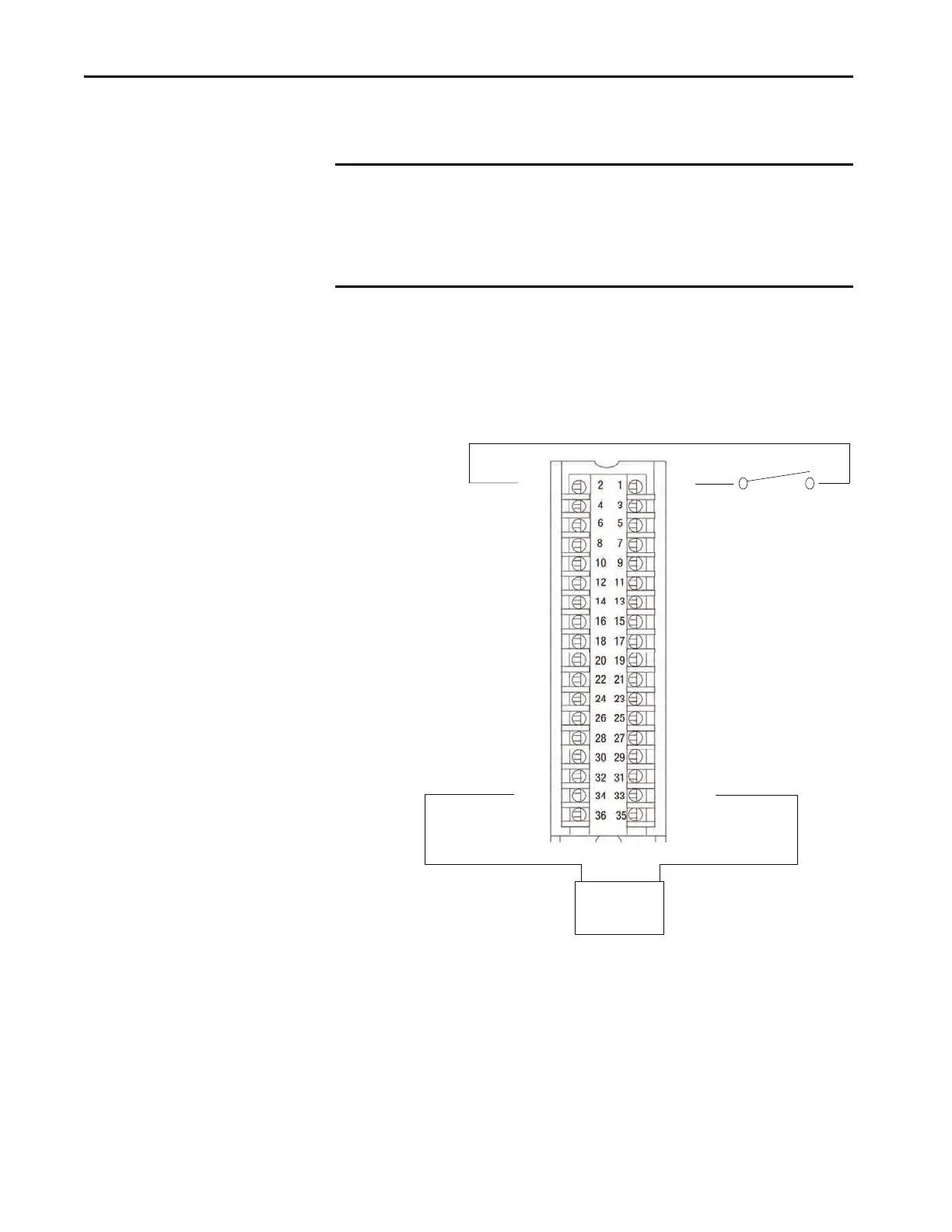
1756-IB16S Module
Wiring Diagrams
You must connect a 24V DC SELV/PELV power source to the DC+/- terminals
to provide field-side power.
When the module is wired as shown, it is suitable for applications that are rated
up to, and including, Category 2 and PLd as defined in ISO 13849-1.
To achieve that suitability rating, you may have to perform diagnostic testing of
the safety function. One diagnostic test method is to configure the safety input
channel for Safety Pulse Test to test the circuit for short circuits to 24V DC.
IMPORTANT • The 24V (DC+ and DC-) power connections are used to supply field-side
power to the module.
• All terminals with the same name are connected together on the module.
For example, DC+ can be connected to either terminal marked DC +.
• Do not physically connect more than two wires to a single RTB terminal.
TO-1
TO-2
TO-3
TO-4
TO-5
TO-6
TO-7
IN-1
IN-2
IN-3
IN-4
IN-5
IN-6
IN-7
IN-8
IN-9
IN-10
IN-11
IN-12
IN-13
IN-14
IN-15
DC(+)
DC(+)
DC(-)
DC(-)
TO-0
TO-1
TO-2
TO-3
TO-4
TO-5
TO-6
TO-7
IN-0
TO-0
+
-
Channel Connections
The diagram shows devices that are connected to safety input channel 0
and test output channel 0. You can connect devices to all 16 channels.
24V DC
SELV/PELV-listed
power supply
 Loading...


