126 Rockwell Automation Publication 1756-UM013B-EN-P - October 2019
Appendix C Application and Wiring Examples for Safety Modules
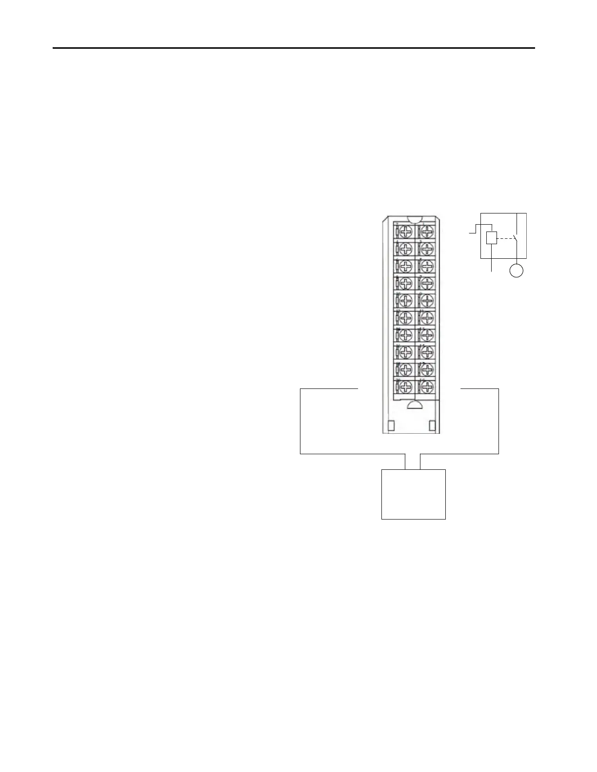
Sourcing Mode
When the module is wired as shown, it is suitable for applications that are rated
up to, and including, Category 2 and PLd as defined in ISO 13849-1.
To achieve that suitability rating, you may have to perform diagnostic testing and
monitoring of the safety function. One diagnostic test method is to configure the
safety output channel for Safety Pulse Test to test the circuit for short circuits to
24V DC.
DC(+)
DC(-)
DC(+)
DC(-)
OUT0-P
OUT1-P
OUT4-P
OUT3-P
OUT2-P
OUT5-P
OUT6-P
OUT7-P
OUT0-M
OUT1-M
OUT2-M
OUT3-M
OUT4-M
OUT5-M
OUT6-M
OUT7-M
+-
K
M
DC –
24V DC
SELV/PELV-listed power
supply
Channel Connections
This wiring example shows connections to Safety Output 0. You
are not limited to using channel 0 in this mode. You can use all
channels as determined by your application.
We strongly recommend that, if you have a direct connection
between the safety output module and an input module and those
modules are powered by separate power supplies, you connect
module DC- and actuator DC- together. This practice helps to
eliminate grounding float from disrupting diagnostics.
 Loading...


