Publication 1762-RM001C-EN-P
14-4 File Instructions
Addressing Modes and File Types can be used as shown in the following
table:
BSL - Bit Shift Left
Instruction Type: output
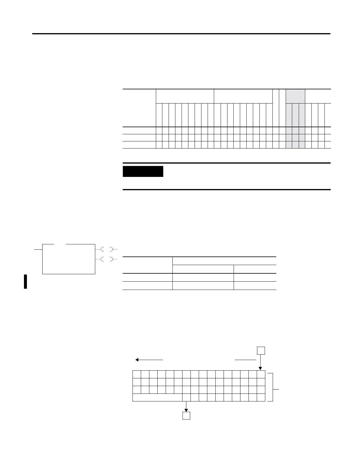
The BSL instruction loads data into a bit array on a false-to-true rung
transition, one bit at a time. The data is shifted left through the array, then
unloaded, one bit at a time. The following figure shows the operation of
the BSL instruction.
Table 14.5 FLL Instruction Valid Addressing Modes and File Types
For definitions of the terms used in this table see Using the Instruction Descriptions on page4-2.
Parameter
Data Files Function Files
CS - Comms
IOS - I/O
Address
Mode
(1)
(1) See Important note about indirect addressing.
Address
Level
O
I
S
B
T, C, R
N
ST
L
MG, PD
RTC
HSC
PTO, PWM
STI
EII
BHI
MMI
DAT
TPI
Immediate
Direct
Indirect
Bit
Word
Long Word
Element
Source •• ••• • • • ••••
Destination •• ••• •
• ••
Length
•
IMPORTANT
You cannot use indirect addressing with: S, ST, MG, PD,
RTC, HSC, PTO, PWM, STI, EII, BHI, MMI, DATI, TPI, CS,
IOS, and DLS files.
EN
DN
BSL
Bit Shift Left
File #B3:1
Control R6:0
Bit Address B32:0/0
Length 1<
BSL
Table 14.6 Execution Time for the BSL Instruction
Controller When Rung Is:
True False
MicroLogix 1200 32
µ
s + 1.3
µ
s/word 1.3
µ
s
MicroLogix 1500 26.1
µ
s + 1.06
µ
s/word 1.4
µ
s
31 30 29 28 27 26 25 24 23 22 21 20 19 18 17 16
47 46 45 44 43 42 41 40 39 38 37 36 35 34 33 32
63 62 61 60 59 58 57 56 55 54 53 52 51 50 49 48
RESERVED 73 72 71 70 69 68 67 66 65 64
Data block is shifted one bit at
a time from bit 16 to bit 73.
Source Bit
I:22/12
58 Bit Array #B3:1
Unload Bit
(R6:0/10)

 Loading...


