Publication 1762-RM001C-EN-P
I/O Configuration 1-9
MicroLogix 1500
Compact™ Expansion
I/O Memory Mapping
Discrete I/O Configuration
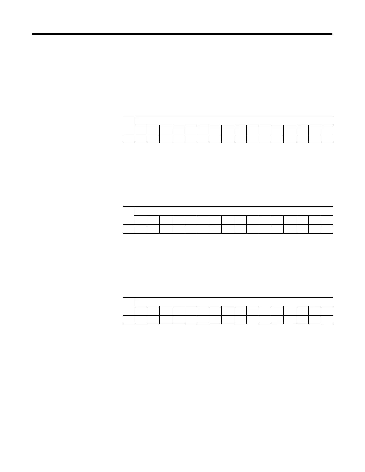
1769-IA8I Input Image
For each input module, the input data file contains the current state of the
field input points. Bit positions 0 through 7 correspond to input terminals
0 through 7, bits 8 through 15 are not used.
r = read, x = not used, always at a 0 or OFF state
1769-IM12 Input Image
For each input module, the input data file contains the current state of the
field input points. Bit positions 0 through 11 correspond to input
terminals 0 through 11, bits 12 through 15 are not used.
r = read, x = not used, always at a 0 or OFF state
1769-IA16 and 1769-IQ16 Input Image
For each input module, the input data file contains the current state of the
field input points. Bit positions 0 through 15 correspond to input
terminals 0 through 15.
r = read
Word
Bit Position
1514131211109876543210
0xxxxxxxxrrrrrrrr
Word
Bit Position
1514131211109876543210
0xxxxrrrrrrrrrrrr
Word
Bit Position
1514131211109876543210
0rrrrrrrrrrrrrrrr

 Loading...


