Publication 1762-RM001C-EN-P
5-4 Using the High-Speed Counter
High-Speed Counter
Function File
Sub-Elements Summary
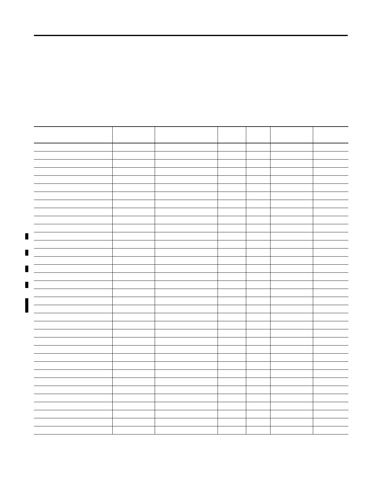
Each HSC is comprised of 36 sub-elements. These sub-elements are either
bit, word, or long word structures that are used to provide control over
the HSC function, or provide HSC status information for use within the
control program. Each of the sub-elements and their respective functions
are described in this chapter. A summary of the sub-elements is provided
in the following table. All examples illustrate HSC0. Terms and behavior
for HSC1 are identical.
Table 5.1 High-Speed Counter Function File (HSC:0 or HSC:1)
Sub-Element Description Address Data Format HSC
Modes
(1)
Function User Program
Access
For More
Information
PFN - Program File Number HSC:0.PFN word (INT) 0 to 7 control read only 5-5
ER - Error Code HSC:0.ER word (INT) 0 to 7 status read only 5-5
UIX - User Interrupt Executing HSC:0/UIX bit 0 to 7 status read only 5-8
UIE - User Interrupt Enable HSC:0/UIE bit 0 to 7 control read/write 5-8
UIL - User Interrupt Lost HSC:0/UIL bit 0 to 7 status read/write 5-9
UIP - User Interrupt Pending HSC:0/UIP bit 0 to 7 status read only 5-9
FE - Function Enabled HSC:0/FE bit 0 to 7 control read/write 5-6
AS - Auto Start HSC:0/AS bit 0 to 7 control read only 5-6
ED - Error Detected HSC:0/ED bit 0 to 7 status read only 5-6
CE - Counting Enabled HSC:0/CE bit 0 to 7 control read/write 5-7
SP - Set Parameters HSC:0/SP bit 0 to 7 control read/write 5-7
LPM - Low Preset Mask HSC:0/LPM bit 2 to 7 control read/write 5-9
HPM - High Preset Mask HSC:0/HPM bit 0 to 7 control read/write 5-11
UFM - Underflow Mask HSC:0/UFM bit 2 to 7 control read/write 5-12
OFM - Overflow Mask HSC:0/OFM bit 0 to 7 control read/write 5-14
LPI - Low Preset Interrupt HSC:0/LPI bit 2 to 7 status read/write 5-10
HPI - High Preset Interrupt HSC:0/HPI bit 0 to 7 status read/write 5-11
UFI - Underflow Interrupt HSC:0/UFI bit 2 to 7 status read/write 5-13
OFI - Overflow Interrupt HSC:0/OFI bit 0 to 7 status read/write 5-14
LPR - Low Preset Reached HSC:0/LPR bit 2 to 7 status read only 5-10
HPR - High Preset Reached HSC:0/HPR bit 2 to 7 status read only 5-12
DIR - Count Direction HSC:0/DIR bit 0 to 7 status read only 5-15
UF - Underflow HSC:0/UF bit 0 to 7 status read/write 5-12
OF - Overflow HSC:0/OF bit 0 to 7 status read/write 5-13
MD - Mode Done HSC:0/MD bit 0 or 1 status read/write 5-15
CD - Count Down HSC:0/CD bit 2 to 7 status read only 5-15
CU - Count Up HSC:0/CU bit 0 to 7 status read only 5-16
MOD - HSC Mode HSC:0.MOD word (INT) 0 to 7 control read only 5-16
ACC - Accumulator HSC:0.ACC long word (32-bit INT) 0 to 7 control read/write 5-22
HIP - High Preset HSC:0.HIP long word (32-bit INT) 0 to 7 control read/write 5-22
LOP - Low Preset HSC:0.LOP long word (32-bit INT) 2 to 7 control read/write 5-22
OVF - Overflow HSC:0.OVF long word (32-bit INT) 0 to 7 control read/write 5-23
UNF - Underflow HSC:0.UNF long word (32-bit INT) 2 to 7 control read/write 5-23
OMB - Output Mask Bits HSC:0.OMB word (16-bit binary) 0 to 7 control read only 5-24
HPO - High Preset Output HSC:0.HPO word (16-bit binary) 0 to 7 control read/write 5-25
LPO - Low Preset Output HSC:0.LPO word (16-bit binary) 2 to 7 control read/write 5-25
(1) For Mode descriptions, see HSC Mode (MOD) on page 5-16.
n/a = not applicable

 Loading...


