Publication 1762-RM001C-EN-P
Using the High-Speed Counter 5-27
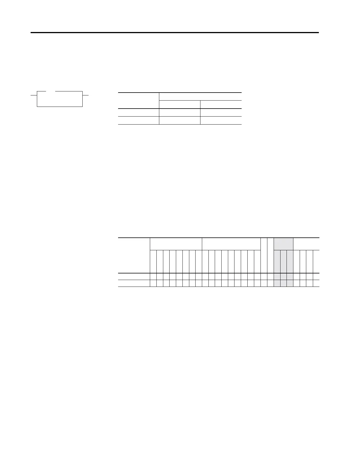
RAC - Reset
Accumulated Value
Instruction Type: output
The RAC instruction resets the high-speed counter and allows a specific
value to be written to the HSC accumulator. The RAC instruction uses the
following parameters:
•
Counter Number - Specifies which high-speed counter is being used:
– Counter Number 0 = HSC0 (MicroLogix 1200 and 1500)
– Counter Number 1 = HSC1 (MicroLogix 1500 only)
•
Source - Specifies the location of the data to be loaded into the HSC
accumulator. The data range is from -2,147,483,648 to 2,147,483,647.
Valid Addressing Modes and File Types are shown below:
RAC
Reset Accumulated Value
Counter HSC0
Source 0
RAC
Controller Execution Time When Rung Is:
True False
MicroLogix 1200 21.2
µ
s0.0
µ
s
MicroLogix 1500 17.8
µ
s0.0
µ
s
Table 5.14 RAC Instruction Valid Addressing Modes and File Types
For definitions of the terms used in this table see Using the Instruction Descriptions on page 4-2.
Parameter
Data Files Function Files
CSF - Comms
IOS - I/O
Address
Mode
Address
Level
O
I
S
B
T, C, R
N
L
MG, PD
RTC
HSC
PTO, PWM
STI
EII
BHI
MMI
DAT
TPI
Immediate
Direct
Indirect
Bit
Word
Long Word
Element
Counter Number •
Source • • • ••

 Loading...


