Publication 1762-RM001C-EN-P
Communications Instructions 21-23
Timing Diagram for the
MSG Instruction
The following section describes the timing diagram for a message
instruction.
1. If there is room in any of the four active message buffers when the
MSG rung becomes true and the MSG is scanned, the EN and EW bits
for this message are set. If this is a MSG write instruction, the source
data is transferred to the message buffer at this time.
(Not shown in the diagram.) If the four message buffers are in use, the
message request is put in the message queue and only the EN bit is
set. The message queue works on a first-in, first-out basis that allows
the controller to remember the order in which the message
instructions were enabled. When a buffer becomes available, the first
message in the queue is placed into the buffer and the EW bit is set
(1).
Once the EN bit is set (1), it remains set until the entire message
process is complete and either the DN, ER, or TO bit is set (1). The
MSG Timeout period begins timing when the EN bit is set (1). If the
timeout period expires before the MSG instruction completes its
function, the ER bit is set (1), and an error code (37H) is placed in the
MG File to inform you of the timeout error.
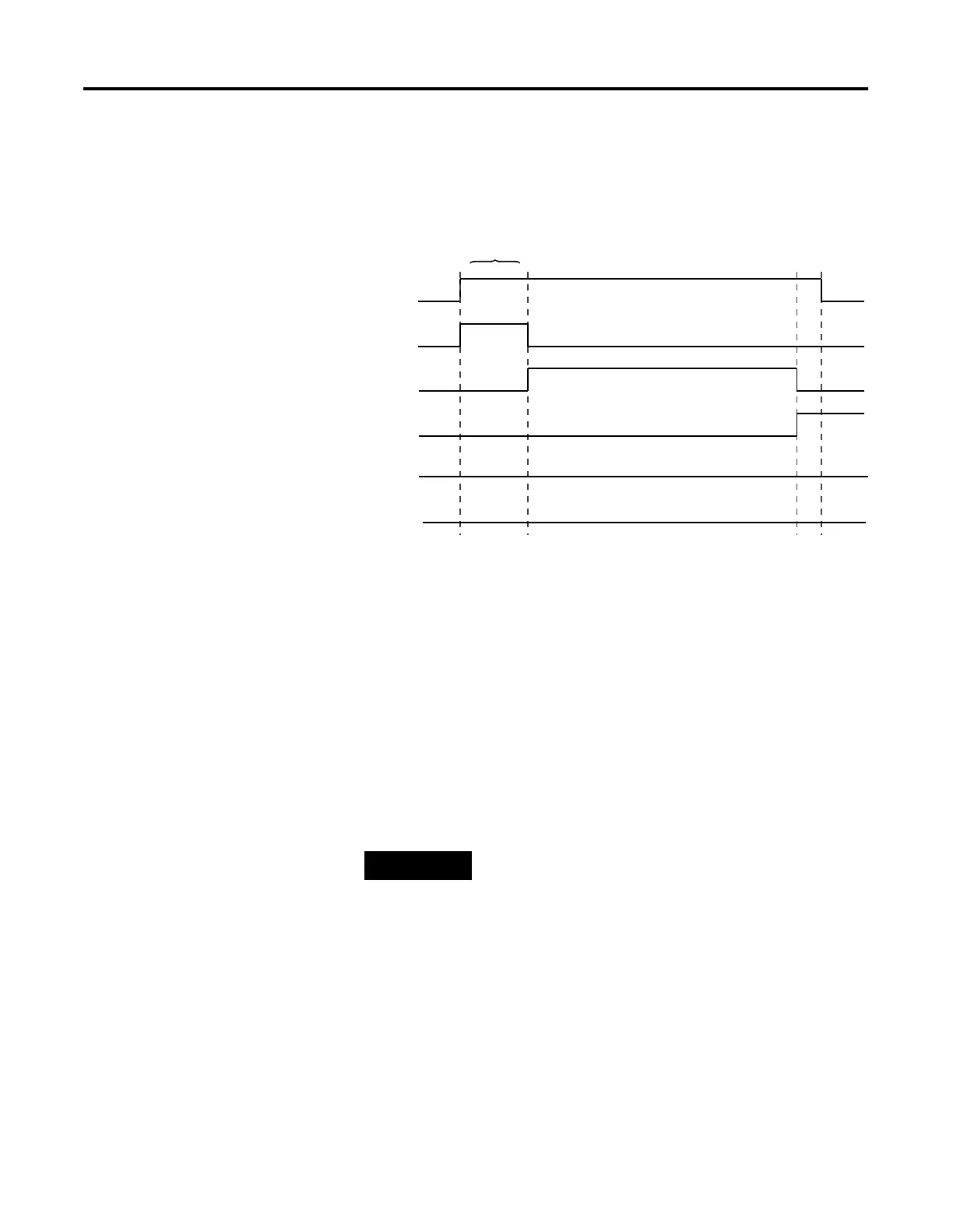
EN
EW
ST
DN
ER
TO
1
0
1
0
1
0
1
0
1
0
1
0
(1) Rung goes true.
(3) Target node
receives packet.
(5) Target node processes packet
successfully and returns data (read)
or acknowledges receipt (write).
(1)
(2) (3)
(5)
(6)
NOTE
The control program does not have access to the
message buffers or the communications queue.

 Loading...


