1 Publication 1764-UM001B-EN-P - April 2002
Appendix
C
Troubleshooting Your System
This chab
pter describes how to troubleshoot your controller. Topics include:
• understanding the controller LED status
• controller error recovery model
• identifying controller faults
• calling Rockwell Automation for assistance
Understanding Controller
LEDs
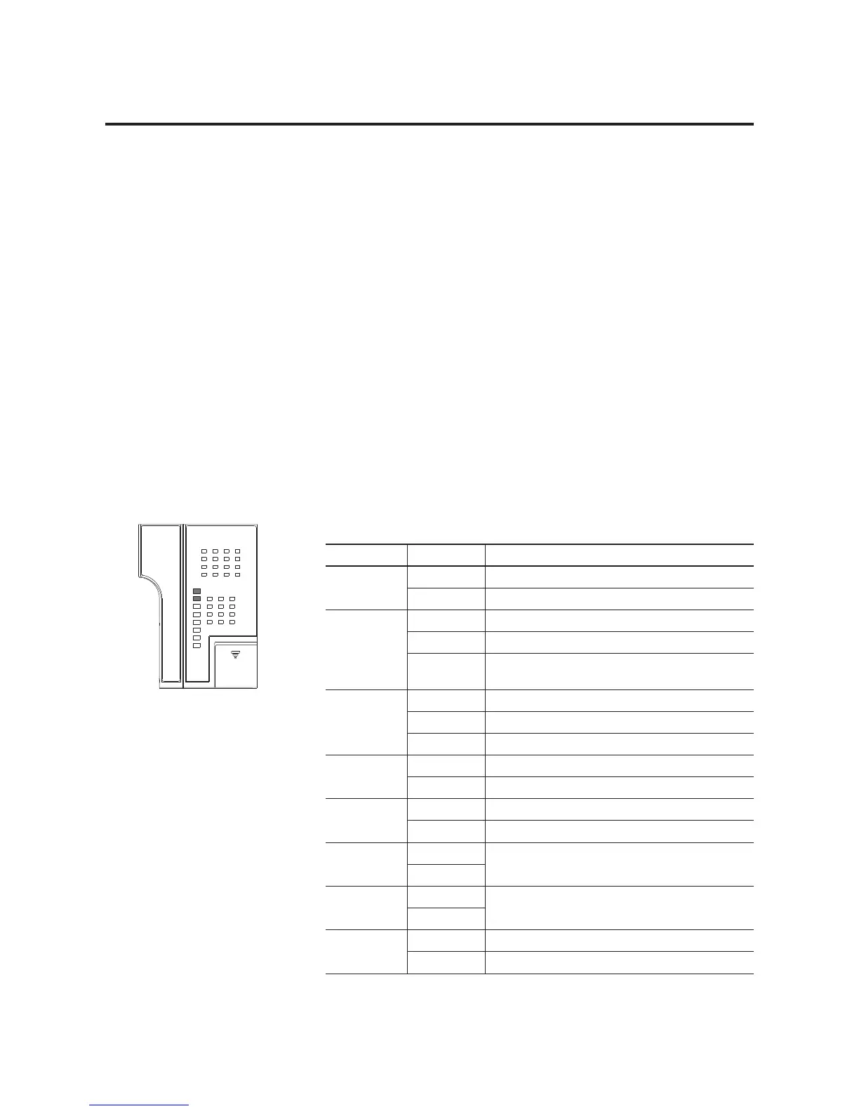
The controller status LEDs provide a mechanism to determine the
current status of the controller if a programming device is not present
or available.
D.C. INPUTS
24V SINK / SOURCE
DC/RELAY OUT
24V SOURCE
POWER
RUN
FAULT
FORCE
BAT. LO
COMM 0
DCOMM
LED Color Indicates
POWER off no input power
green power on
RUN off controller is not in Run mode or REM Run
green controller is in Run mode or REM Run
green flashing system is not in Run mode; memory module transfer is
in progress
FAULT off no fault detected
red flashing faulted user program
red processor hardware fault or critical fault
FORCE off no forces installed
amber forces installed
BATTERY LOW off battery OK
red battery needs replacement (See page B-2.)
COMM 0 off flashes when communications are active
green
COMM 1
(1764-LRP only)
off flashes when communications are active
green
DCOMM
(1)
off user configured communications mode is active
green default communications mode active

 Loading...


