Publication 1764-UM001B-EN-P - April 2002
2-14 Installing Your Controller
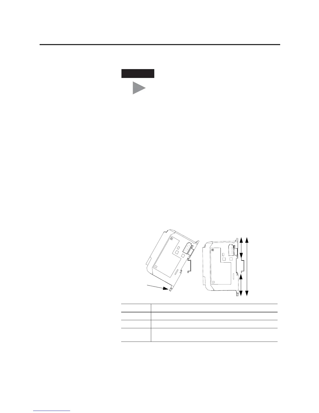
Using a DIN Rail
The base unit and expansion I/O DIN rail latches lock in the open
position so that an entire system can be easily attached to or removed
from the DIN rail. The maximum extension of the latch is 15 mm (0.67
in.) in the open position. A flat-blade screw driver is required for
removal of the base unit. The base can be mounted to
EN50022-35x7.5 or EN50022-35x15 DIN rails. DIN rail mounting
dimensions are shown below.
TIP
If additional I/O modules are required for the
application, remove the ESD barrier to install
expansion I/O modules. A maximum of 16 I/O
modules may be connected to the base. (See page
1-7 for system requirements.) The I/O module’s
current requirements and power consumption may
further limit the number of modules connected to
the base. See System Loading and Heat Dissipation
on page F-1. An end cap terminator (catalog number
1769-ECR or 1769-ECL) is required at the end of the
group of I/O modules attached to the base.
Dimension Height
A DIN latch open: 138 mm (5.43 in.), DIN latch closed: 118 mm (4.65 in.)
B 47.6 mm (1.875 in.)
C 47.6 mm (1.875 in) DIN latch closed
54.7 mm (2.16 in.) DIN latch open
B
C
A
DIN Rail Latch

 Loading...


