Publication 1764-UM001B-EN-P - April 2002
Using Trim Pots and the Data Access Tool (DAT) 5-5
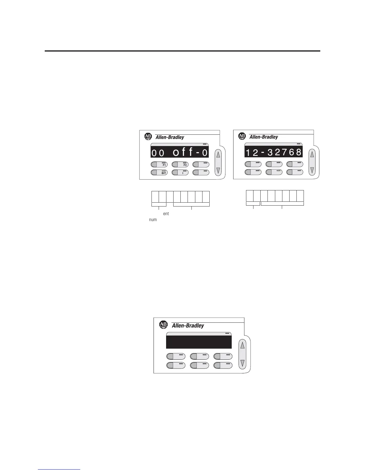
Understanding the DAT Display
When the DAT enters either the bit or integer mode, the element
number and its data are displayed, as shown below. The element
number is either the integer or bit location.
If the displayed element is defined in the controller’s data file, and is
not protected, the element number flashes, indicating that it can be
modified. If the displayed element is protected, the PROTECTED
indicator light illuminates, and the element number does not flash,
indicating that the element cannot be modified.
If the element is undefined, the data field displays three dashes. The
element number does not flash because the element does not exist.
F1
BIT
F2
INT
ESC
ENTER
PROTECTED
21
3
276
-
8
F1
BIT
F2
INT
ESC
ENTER
PROTECTED
00
o
ff
-
0
bit element
number
• 0 to 47
bit data
• OFF - 0
• ON - 1
• – – – (undefined)
integer
element
number
• 0 to 47
integer data
• -32,768 to 32,767
• – – – (undefined)
Bit Mode Display Integer Mode Display
F1
BIT
F2
INT
ESC
ENTER
PROTECTED
50
---

 Loading...


