Publication 1764-UM001B-EN-P - April 2002
F-2 System Loading and Heat Dissipation
Selecting System Devices
1. Use Table F.1 to select the processor and optional
communications or display devices. Enter a 1 in the “Select
Devices” column.
2. Enter the current draw values in the “Calculated Current for
System” columns. If an external power supply will be used to
power communication devices, do not include their current
draw values in this calculation. Add up the current draw values
to determine the “SUBTOTAL1” values.
3. Use Table F.2 to select the I/O modules. Enter the number of
modules in either the “Base Unit Expansion” or the “Bank 1”
column.
Depending on its configuration, the 1769-SDN may transfer large
amounts of data into and out of the controller I/O image tables.
Care should be taken when using more than three of these
modules to verify that they are optimally configured. This will
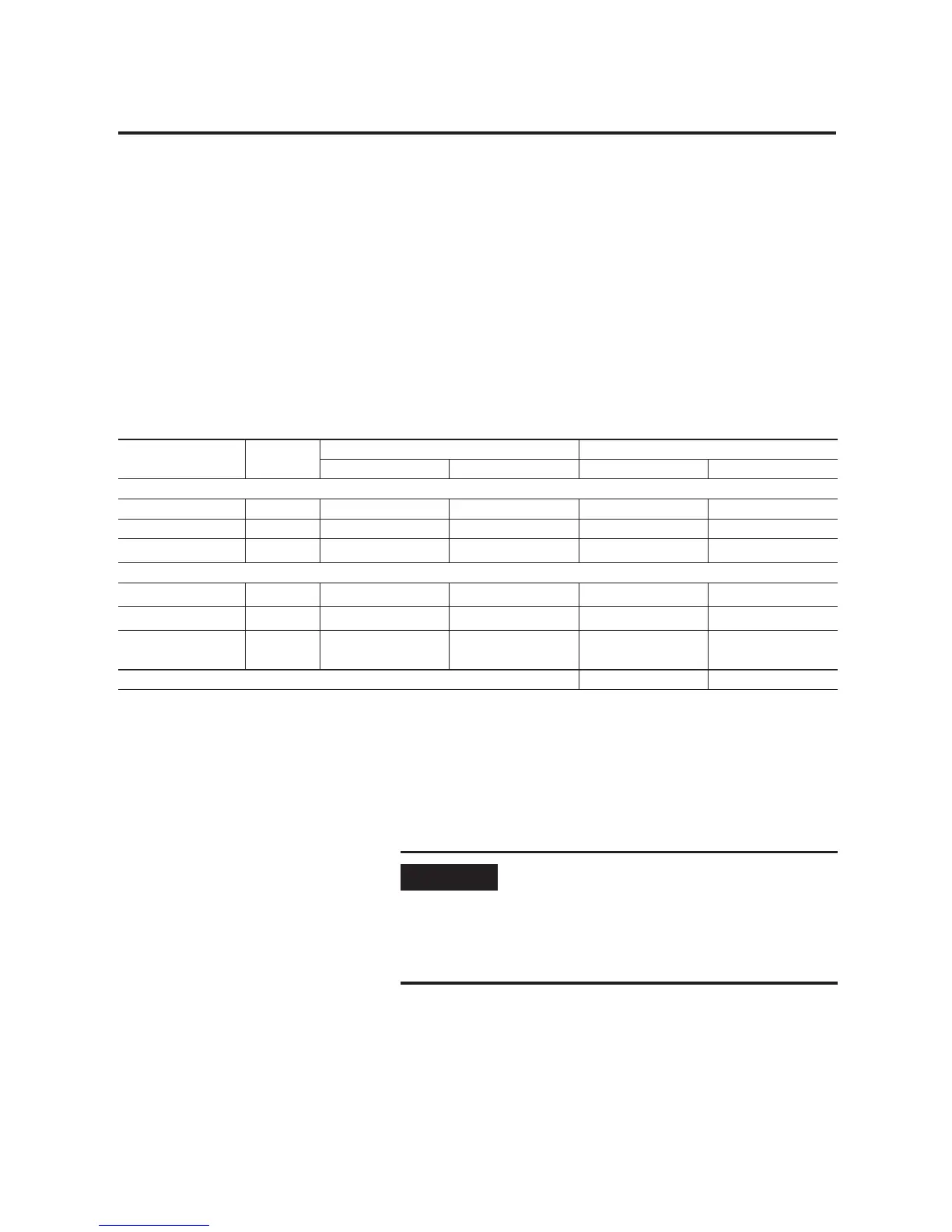
Table F.1 Selecting Hardware: Base Unit and Communications/Display Devices
Catalog Number Select
Device(s)
Bus Current Draw Specification Calculated Current for System
at 5V dc (mA) at 24V dc (mA) at 5V dc (mA) at 24V dc (mA)
Choose a Processor, LSP or LRP:
1764-LSP 300 0
1764-LRP 380 0
1764-DAT
(1)
optional
350 0
Communications/Display Devices, optional, one only maximum:
1761-NET-AIC
(1)
0
120
(2)
1761-NET-ENI
(1)
0
100
(2)
2707-MVH232 or
2707-MVP232
(1)
0
80
(2)
SUBTOTAL1 (A1) (B1)
(1) These are optional accessories. Current is consumed only if the accessory is installed.
(2) Current for the AIC+ and ENI may be supplied by controller communications port or from an external 24V dc source. No current is consumed from the controller when a
user-supplied, external source is used. If an external source is to be used, do not select the device here. The current for a 2707-MVH232 or 2707-MVP232 MicroView
Operator Interface is supplied from the controller communication port, when directly connected.
IMPORTANT
When planning the system layout, keep in
mind that each module has a “Power Supply
Distance Rating”. This is the maximum distance
an I/O module may be located from the power
supply. For most modules, the rating is 8. For
the 1769-HSC and 1769-SDN, the rating is 4.

 Loading...


