Rockwell Automation Publication 22-TD001I-EN-P - June 2013 15
PowerFlex 4 and 40 AC Drives
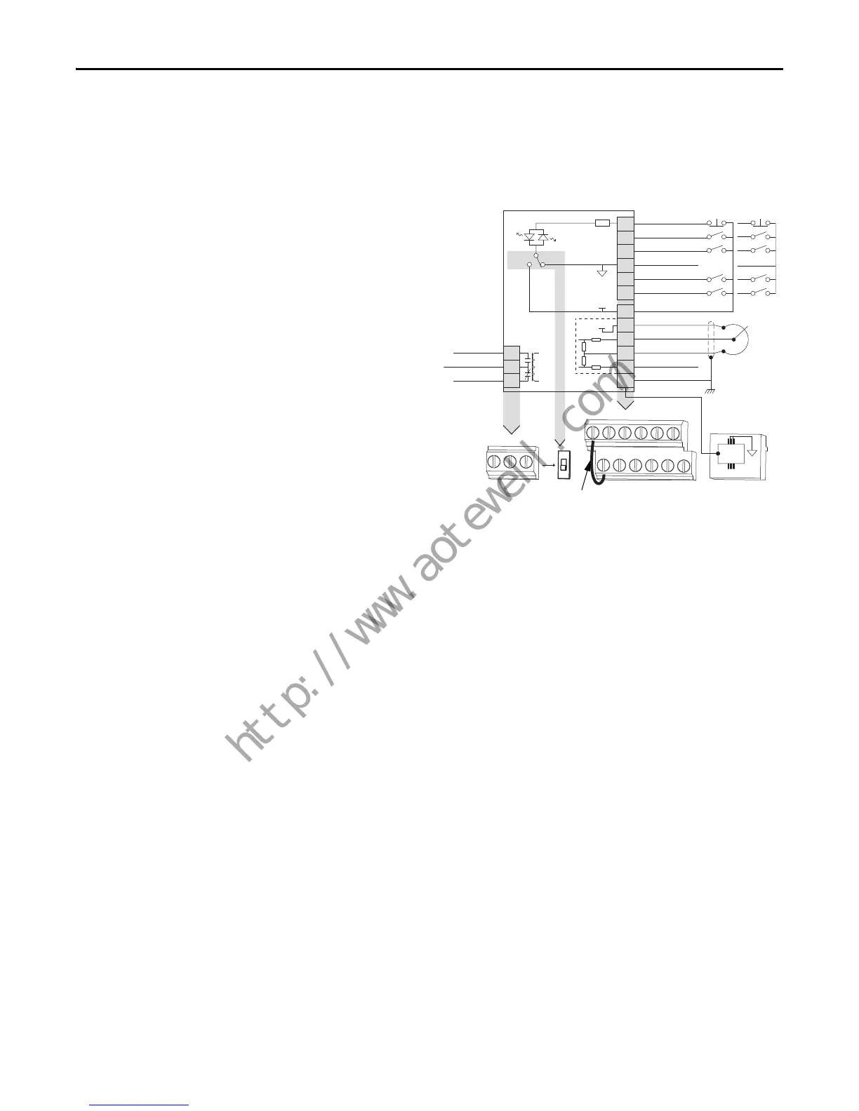
Control Wiring
PowerFlex 4
• The control logic is 24V DC and can be set for either
Sink or Source control via a DIP switch setting.
• Control terminal screws are sized for a conventional
blade screw driver.
• I/O Terminals 1, 2 and 3 are dedicated for Stop, Start
and Reverse operation respectively. These I/O
Terminals can be programmed for 2- or 3-Wire
operation to meet application requirements.
• I/O Terminals 4 and 5 are programmable and provide
added flexibility. Programmable functions include:
– Local Control
– Preset Frequencies
– Jog
– RS485 Control
– Second Accel/Decel
– Auxiliary Fault
– Clear Fault
• Speed can be controlled via a 0…10V input or 4…20
mA input. Both are electrically isolated from the drive.
• One form C relay can be programmed to provide the
status of a wide variety of drive conditions.
• The drive is shipped with a jumper installed between
I/O Terminals 01 and 11 to allow out of box operation
from the keypad.
01
02
03
04
05
06
11
12
13
14
15
16
Stop
Start/Run FWD
Dir/Run REV
Digital Common
Digital Input 1
Digital Input 2
R1
R2
R3
Relay N.O.
Relay Common
Relay N.C.
+24V DC
+10V DC
0-10V In
Analog Common
4-20mA In
RS485 Shield
+24V
+10V
SRCSNK
Typical
SNK Wiring
Typical
SRC Wiring
81
RS485
(DSI)
R1 R2 R3
01 02 03 04 05 06
11 12 13 14 15 16
SNK
SRC

 Loading...


