Rockwell Automation Publication 22-TD001I-EN-P - June 2013 17
PowerFlex 4 and 40 AC Drives
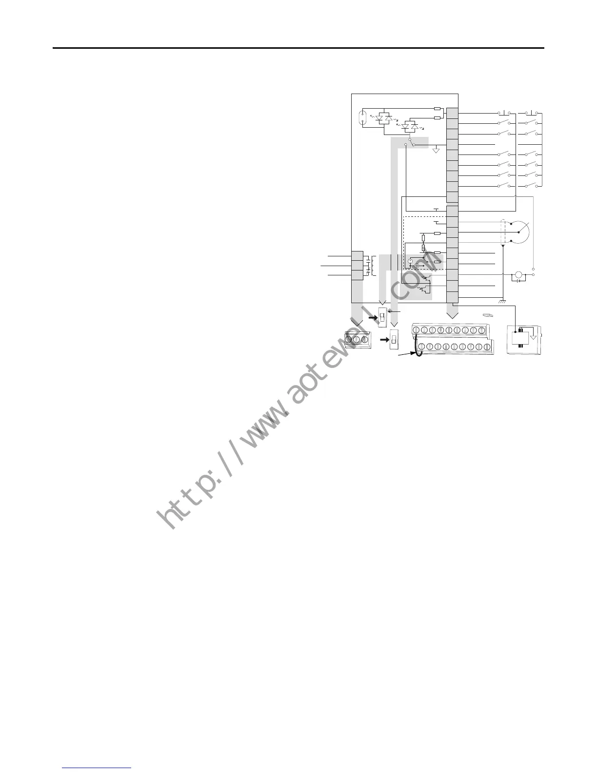
PowerFlex 40
• The control logic is 24V DC and can be set for either
Sink or Source control via a DIP switch setting.
• Control terminal screws are sized for a conventional
blade screw driver.
• I/O Terminals 1, 2 and 3 are dedicated for Stop, Start and
Reverse operation respectively. These I/O Terminals can
be programmed for 2- or 3-Wire operation to meet
application requirements.
• I/O Terminals 5, 6, 7 and 8 are programmable and
provide added flexibility. Programmable functions
include Local Control, Jog, Second Accel/Decel, Clear
Fault, Preset Frequencies, RS485 Control and Auxiliary
Fault.
• Speed can be controlled via a 0…10V input and/or 4…20
mA input. Both inputs are independently isolated from
the rest of the drive and can be used for applications such
as PID. Voltage input can be programmed for bipolar
operation.
• The drive is shipped with a jumper installed between I/O
Terminals 01 and 11 to allow out of box operation from
the keypad.
04
05
06
07
01
02
03
08
09
11
12
13
14
15
16
17
18
19
Digital Common
Digital Input 1
Digital Input 2
Digital Input 3
Stop
(1)(4)
Start/Run FWD
(2)
Direction/Run REV
Digital Input 4
Opto Common
R1
R2
R3
Relay N.O.
Relay Common
Relay N.C.
+24V DC
+10V DC
0-10V (or ±10V) Input
Analog Common
4-20mA Input
Analog Output
Opto Output 1
Opto Output 2
RS485 Shield
+24V
+10V
Typical
SNK Wiring
Typical
SRC Wiring
1
RS485
(DSI)
R1 R2 R3
SNK
SRC
0-10V
0-20mA
01 02 03 04 05
11 12 13 14 15
06 07 08 09
16 17 18 19
Enable
(4)
Jumper
30V DC
50mA
Non-inductive
Common
24V
ENBL
Enable
(4)
Jumper
(3)
Pot must be
1-10k ohm
2 Watt Min.
0-10V
0/4-20mA
Analog Output Select
SRCSNK

 Loading...


