Publication 20A-IN009C-EN-P
PowerFlex® 70 Adjustable Frequency AC Drive Installation Instructions 21
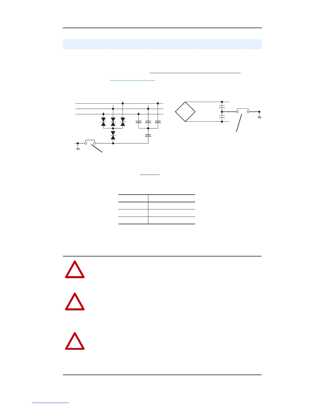
The PowerFlex 70 drive contains protective MOVs and Common Mode
Capacitors referenced to ground (see below). To guard against unstable
operation and/or damage, the drive must be properly configured
as
shown in Table I on page 22.
Important: All PowerFlex 70 240, 480 & 600V AC input drives are
shipped without
the DC bus common mode capacitors
referenced to ground. Specific drive catalog numbers are
listed below:
See Wiring and Grounding Guidelines for PWM AC Drives, publication
DRIVES-IN001 for information on ungrounded systems.
Before proceeding, ensure that all power to the drive has been removed.
Disconnecting MOVs and Common Mode Capacitors
R/L1
S/L2
T/L3
DC+
DC–
MOV and AC EMI Capacitor Phase to Ground
Common Mode Capacitor to Ground
Jumper-Wire
Jumper-Wire
Voltage Cat. No.
240 20AB…
480 20AD…
600 20AE…
!
ATTENTION: Only qualified personnel familiar with adjustable
frequency AC drives and associated machinery should perform
maintenance/repair of the system. Failure to comply may result in
personal injury and/or equipment damage.
!
ATTENTION: To avoid an electric shock hazard, verify that the
voltage on the bus capacitors has discharged before performing any
work on the drive. Measure the DC bus voltage at the +DC & –DC
terminals of the Power Terminal Block (refer to the User Manual for
location). The voltage must be zero.
!
ATTENTION: The following information is merely a guide for proper
installation. Rockwell Automation cannot assume responsibility for the
compliance or the noncompliance to any code, national, local or
otherwise for the proper installation of this drive or associated
equipment. A hazard of personal injury and/or equipment damage
exists if codes are ignored during installation.

 Loading...


