Publication 20A-IN009C-EN-P
PowerFlex® 70 Adjustable Frequency AC Drive Installation Instructions 41
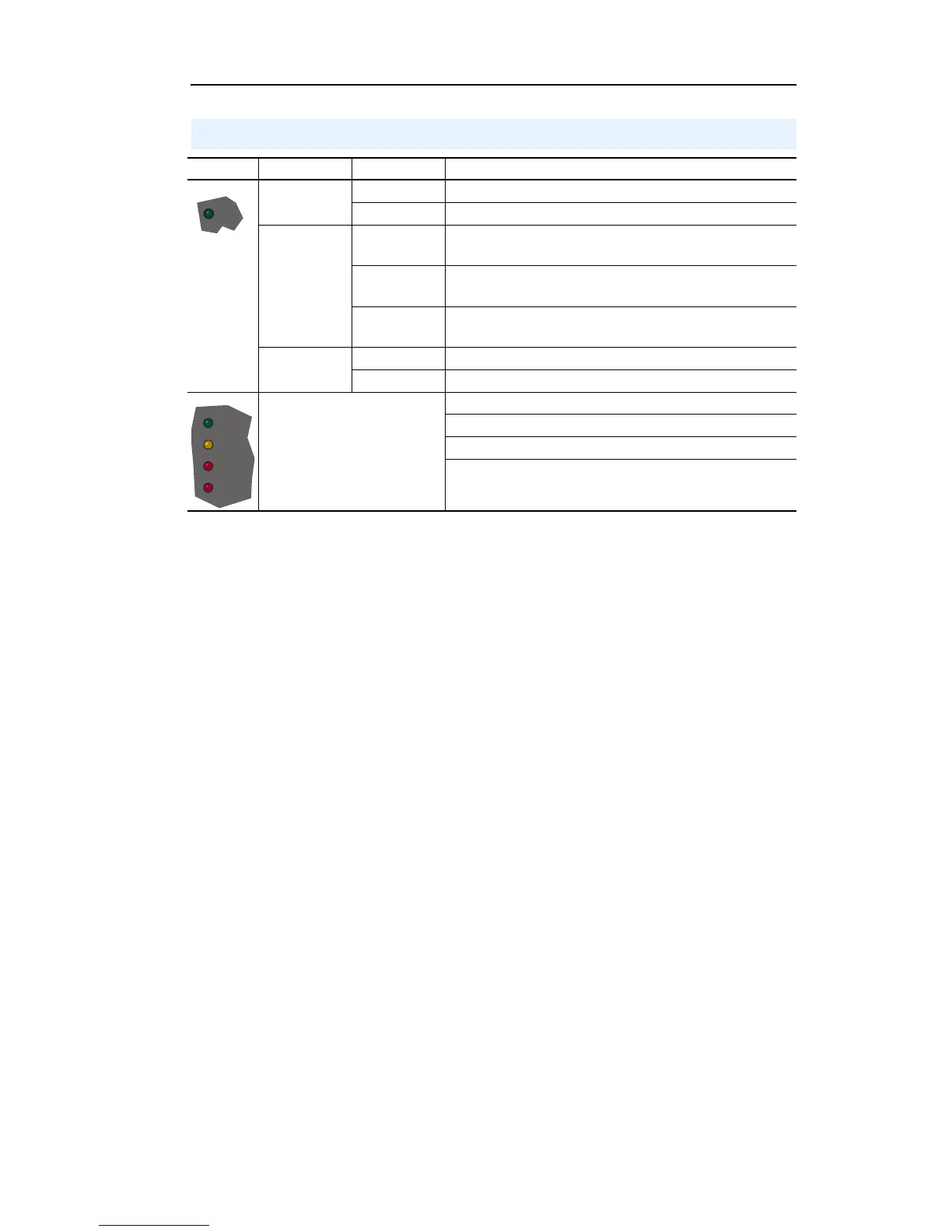
Drive Status Indicators
Name Color State Description
Green Flashing Drive ready, but not running and no faults are present.
Steady Drive running, no faults are present.
Yellow Flashing,
Drive Stopped
An inhibit condition exists, the drive cannot be started.
Check parameter 214 [Start Inhibits].
Flashing,
Drive Running
An intermittent type 1 alarm condition is occurring.
Check parameter 211 [Drive Alarm 1].
Steady,
Drive Running
A continuous type 1 alarm condition exists.
Check parameter 211 [Drive Alarm 1].
Red Flashing A fault has occurred.
Steady A non-resettable fault has occurred.
Refer to the Communication
Adapter User Manual.
Status of DPI port internal communications (if present).
Status of communications module (when installed).
Status of network (if connected).
Status of secondary network (if connected).
STS
PORT
MOD
NET A
NET B

 Loading...


