Publication 20A-IN009C-EN-P
PowerFlex® 70 Adjustable Frequency AC Drive Installation Instructions 33
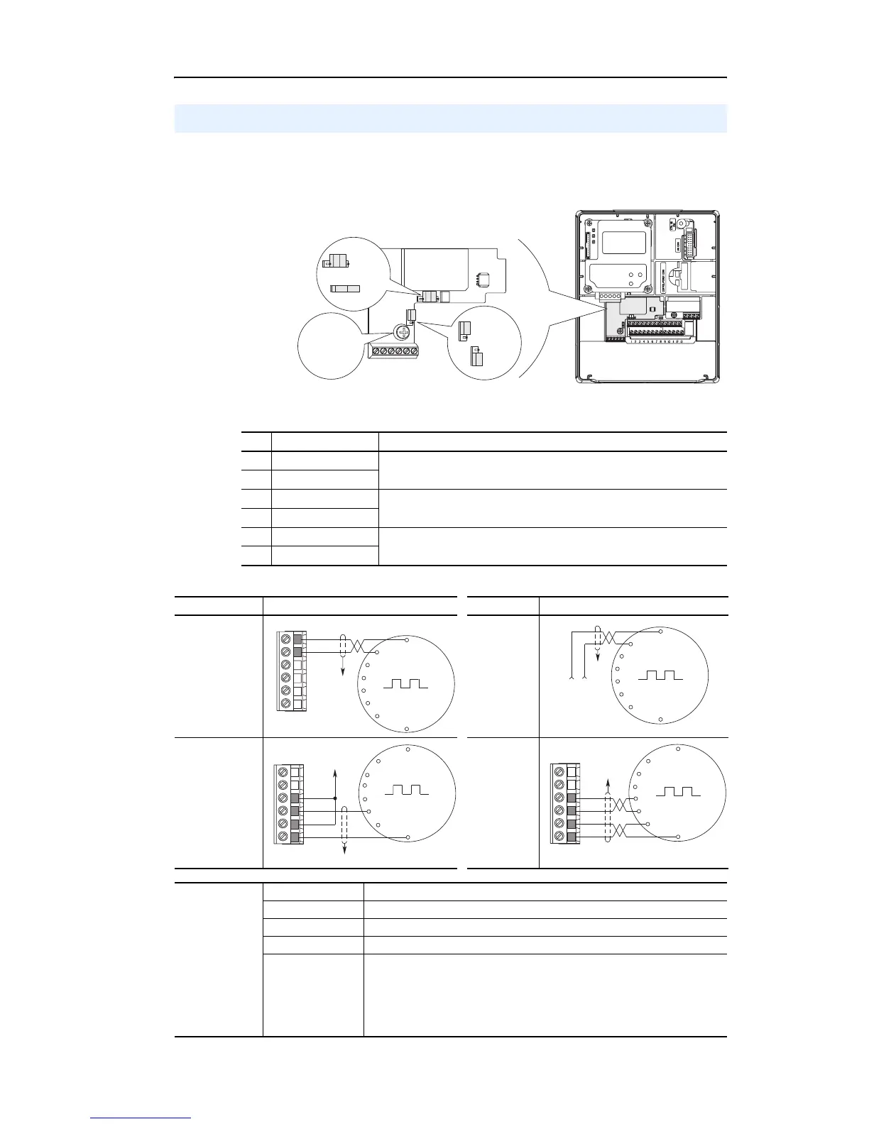
The optional PowerFlex Encoder Interface can source 5 or 12 volt power
and accept 5 or 12 volt single ended differential inputs. Factory default
setting is 12 volts.
Table L Terminal Description
Figure 4 Sample Encoder Wiring
Encoder Interface Option (Enhanced Control Only)
No. Signal Description
1 5-12V Power
Internal power source 250 mA (isolated).
2 Power Return
3 Encoder B (NOT)
Single channel or quadrature B input.
4 Encoder B
5 Encoder A (NOT)
Single channel or quadrature A input.
6 Encoder A
6
1
= 12V
= 5V
= 12V
= 5V
20A-ENC-1
0.8…1.1 N•m
(7…10 lb•in)
Receive Voltage
Send Voltage
I/O Connection Example I/O Connection Example
Encoder
Power –
Internal Drive
Power
Internal (drive)
12V DC,
250mA
Encoder
Power –
External
Power
Source
Encoder
Signal –
Single-Ended,
Dual Channel
Encoder
Signal –
Differential,
Dual
Channel
Common
+12V DC
(250 mA)
6
5
4
3
2
1
to SHLD
+
Common
External
Power
Supply
to
SHLD
A NOT
A
B
B NOT
to SHLD
to Power Supply
Common
6
5
4
3
2
1
to SHLD
6
5
4
3
2
1
A NOT
B
A
B NOT
Encoder
Specifications
Type: Incremental, dual channel
Supply: 5V/12V Configurable +/-5%
Quadrature: 90° +/-27°
Duty Cycle: 50% +10%
Requirements Encoders must be line driver type, quadrature (dual channel) or pulse
(single channel), single-ended or differential and capable of supplying a
minimum of 10 mA per channel. The Encoder Interface Board accepts 5V or
12V DC square-wave with a minimum high state voltage of 3.5V DC (5V
mode) and 7.0V DC (12V mode). Maximum low state voltage is 1V DC (for
both 5V and 12V modes). Maximum input frequency is 250 kHz.

 Loading...


