Publication 20A-IN009C-EN-P
34 PowerFlex® 70 Adjustable Frequency AC Drive Installation Instructions
• This check list supports the Basic Start-Up menu option. See page 39
for information on other start-up routines.
• A Human Interface Module (HIM) is required to run the Basic
Start-Up routine.
• The Basic Start-Up routine may modify parameter values for Analog
and Digital I/O. Refer to Common I/O Programming Changes on
page 42
.
❏ 1. Verify input supply voltage.
❏ 2. Check output wiring.
❏ 3. Check control wiring.
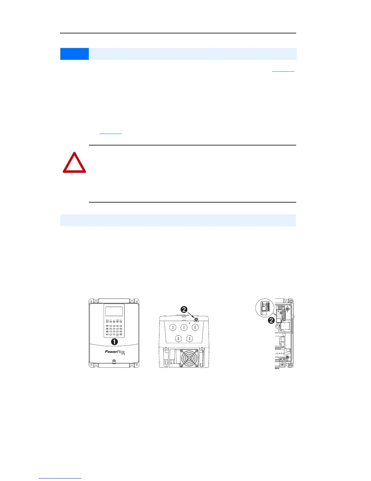
❏ 4. Connect a Human Interface Module (HIM) to DPI Port 1 or 2.
Figure 5 DPI Ports ➊ and ➋
Step 5 Start-Up Check List
!
ATTENTION: Power must be applied to the drive to perform the
following start-up procedure. Some of the voltages present are at
incoming line potential. To avoid electric shock hazard or damage to
equipment, only qualified service personnel should perform the
following procedure. Thoroughly read and understand the procedure
before beginning.
Prepare For Drive Start-Up
CTRL BD
GND
Optional Service
Connection Board
(SK-M9-SCB1)
provides temporary
DPI connection with
drive cover removed.

 Loading...


