Rockwell Automation Publication 750-IN100B-EN-P - July 2017 107
Power Wiring Chapter 5
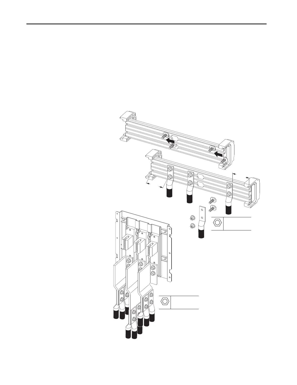
Bus Bar Connections
AC line input power and output motor cables with appropriate barrel lugs are
connected directly to bus bars and use the fastening hardware provided. Keep
the wire connections at least 51 mm (2 in.) away from the ends of the slotted
bus bar. Clamp kits, SK-RM-GRNDCLMP-nn, are available for making
connections to the PE ground bar.
Fastening hardware can be inserted into the channel of slotted bus bar through
the notched area in the center of the bus bar, if provided, or at the end of the
bus bar.
Frame 8 Cable Connections
Customer-supplied M12 hardware.
Insert fastening hardware into the bas bar channel at the
center notch, if accessible, or at the end of the bus bar.
M10
15 mm
38 N•m (336 lb•in)
M12
19 mm
38 N•m (336 lb•in)

 Loading...


