56 Rockwell Automation Publication 750-IN100B-EN-P - July 2017
Chapter 3 Prepare for Installation
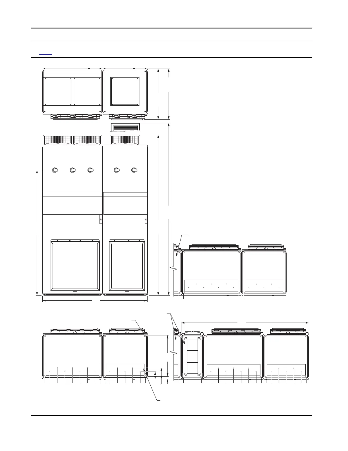
Frame 12 Top, Front, and Bottom Views - Dimensions are mm (in.)
See page 57
for optional exit wire bay dimensions.
65 (2.6)
65 (2.6)
300 (11.8)
0 (0)
235 (9.3)
68 (2.7)
168 (6.6)
268 (10.6)
368 (14.5)
468 (18.4)
868 (34.2)
968 (38.1)
1068 (42.0)
1168 (46.0)
1268 (50.0)
568 (22.4)
668 (26.3)
0 (0)
735 (28.9)
800 (15.7)
1335 (52.6)
1661
(65.4)
0 (0)
735 (28.9)
800 (15.7)
1335 (52.6)
1035 (40.7)
1100 (43.3)
1635 (64.4)
368 (14.5)
468 (18.4)
568 (22.4)
668 (26.3)
768 (30.2)
1168 (46.0)
1268 (49.9)
1368 (53.9)
1468 (57.8)
1568 (61.7)
868 (34.2)
968 (38.1)
IP21, UL Type 1
2132
(83.9)
IP54, UL Type 12
2291
(90.2)
IP21, UL Type 1
676
(26.6)
IP54, UL Type 12
721
(28.4)
1400
(55.1)
1700
(66.9)
36
(1.4)
150
(5.9)
105
(4.1)
535
(21.1)
Adjacent enclosure
Adjacent enclosure and control bay
Mounting Holes
Motor Cables - Bottom Exit
(Plate is marked with recommended gland or conduit hole pattern.)
Power BayPower Bay

 Loading...


