Rockwell Automation Publication 750-IN100B-EN-P - July 2017 127
Power Wiring Chapter 5
Bypass Contactor Precaution
Applying and Removing
Power
Drive Power Jumper
Configuration
PowerFlex 755T products contain protective MOVs and common mode
capacitors. To guard against drive damage and/or operational problems, these
devices must be properly configured according to the tables in this section. To
connect or disconnect these devices, refer to the jumper configurations shown
in the figures on pages 131
…133.
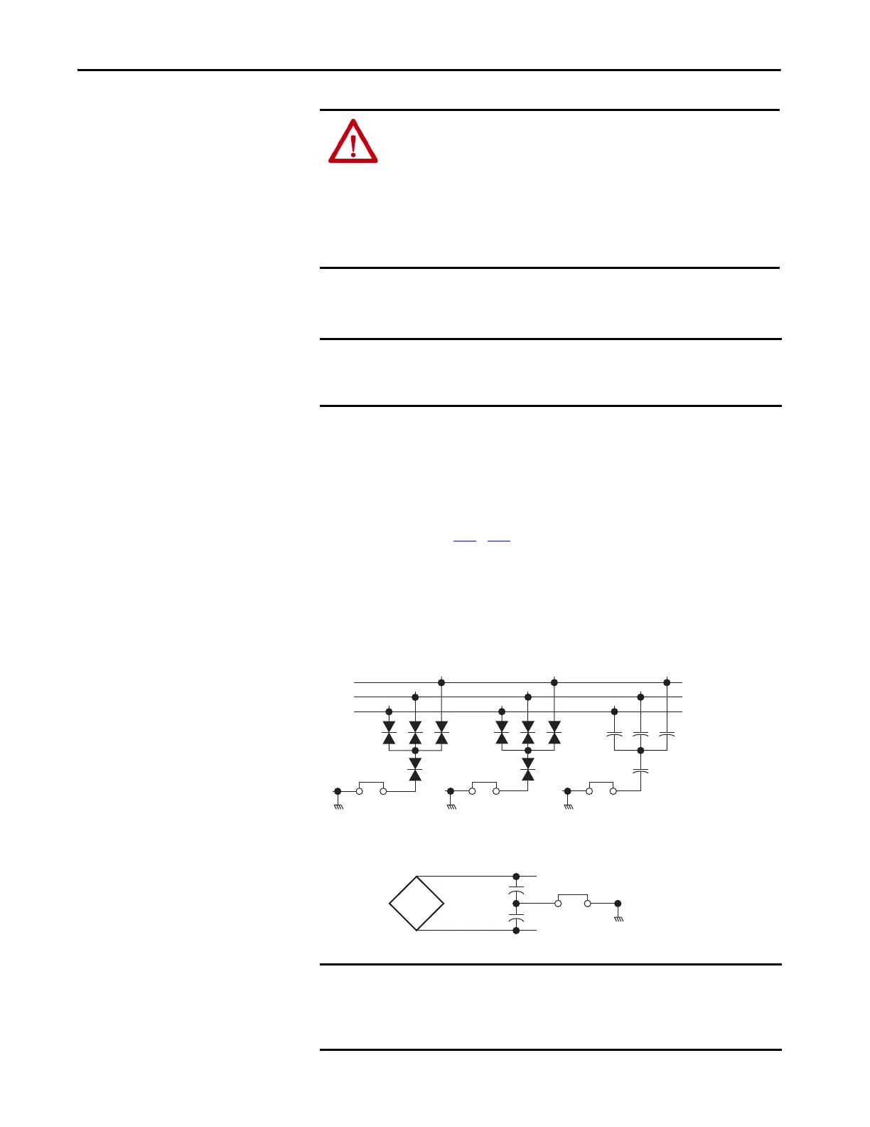
MOV and Common Mode Capacitor Circuits
Figure 63 - MOV and AC EMI and Common Mode Capacitor Circuits
ATTENTION: An incorrectly applied or installed bypass system can result in
component damage or reduction in product life. The most common causes
are:
• Wiring AC line to drive output or control terminals.
• Improper bypass or output circuits not approved by Allen-Bradley.
• Output circuits which do not connect directly to the motor.
Contact Allen-Bradley for assistance with application or wiring.
IMPORTANT Wait 90…180 seconds before cycling power disconnect switches. This
requirement applies to both Off-to-On and On-to-Off transitions. Rapid
power cycling may result in equipment damage.
IMPORTANT By default, the PE-A, PE-A1 and PE-A2 jumpers are installed in the
connected (IN) position. By default, the PE-B1 jumper is installed in the
disconnected (OUT) position. If necessary, reconfigure this jumper as
determined by the power source type available.
MOV and AC Common Mode Capacitor
DC Common Mode Capacitor

 Loading...


