EasyManuals Logo
Home>Allen-Bradley>Controller>PowerFlex 700AFE

Allen-Bradley PowerFlex 700AFE Installation Instructions

Allen-Bradley PowerFlex 700AFE
192 pages
To Next Page IconTo Next Page
To Previous Page IconTo Previous Page
Page #94 background imageLoading...
Page #94 background image
94 Rockwell Automation Publication 750-IN100B-EN-P - July 2017
Chapter 4 Mechanical and Electrical Installation
Electrical Interconnections
After the product enclosures are mechanically joined and properly anchored to
the mounting surface, electrically connect the enclosures together. There are
five electrical interconnections that are required:
•AC bus
•DC bus
•Control bus
•PE ground
Fiber-optic connections
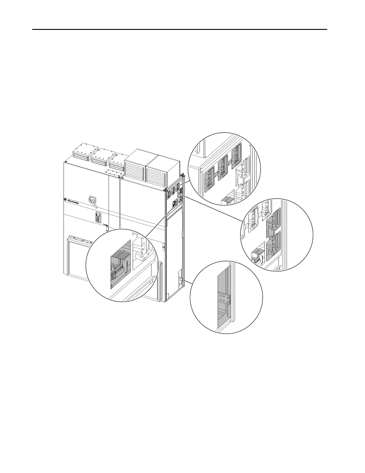
Figure 48 - Bus Bar Locations
PE Ground Bus Bar
DC Bus Bars
AC Power Supply Bus Bars
Control Bus Bars and
Fiber-optic Guide

Table of Contents

Other manuals for Allen-Bradley PowerFlex 700AFE

Questions and Answers:

Question and Answer IconNeed help?

Do you have a question about the Allen-Bradley PowerFlex 700AFE and is the answer not in the manual?

Allen-Bradley PowerFlex 700AFE Specifications

General IconGeneral
BrandAllen-Bradley
ModelPowerFlex 700AFE
CategoryController
LanguageEnglish

Related product manuals