EasyManuals Logo
Home>Allen-Bradley>Controller>PowerFlex 700AFE

Allen-Bradley PowerFlex 700AFE Installation Instructions

Allen-Bradley PowerFlex 700AFE
192 pages
To Next Page IconTo Next Page
To Previous Page IconTo Previous Page
Page #64 background imageLoading...
Page #64 background image
64 Rockwell Automation Publication 750-IN100B-EN-P - July 2017
Chapter 4 Mechanical and Electrical Installation
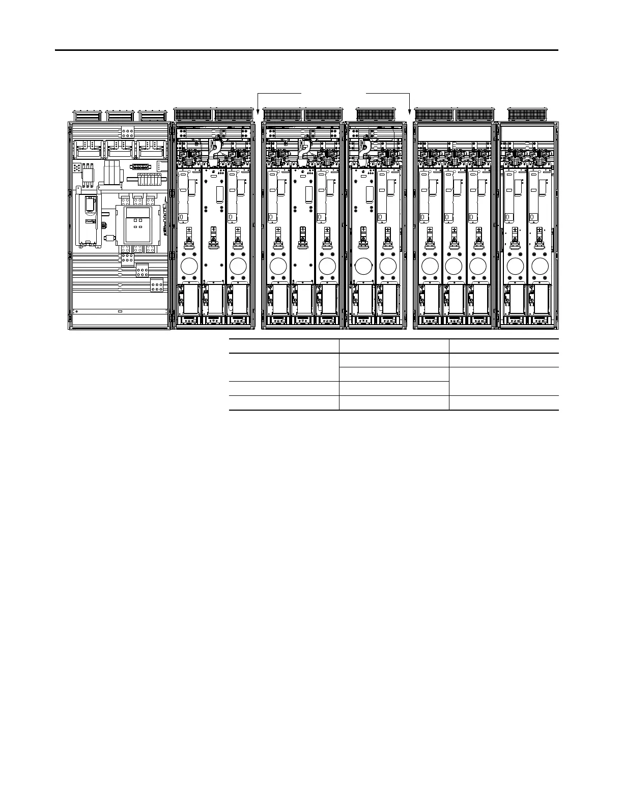
Figure 23 - Frame 12 Drives
M1M0L1L0 L3 LCL2L2 L4 M2 M3 M4
Shipping Splits
Module Type Remove Position No. Shipping Split Section
Line side converter L0, L1 Section 1 of 3 (left section)
L2, L3 Section 2 of 3 (center section)
LCL filter LCL2
Motor side inverter M0, M1, M2, M3, M4 Section 3 of 3 (right section)

Table of Contents

Other manuals for Allen-Bradley PowerFlex 700AFE

Questions and Answers:

Question and Answer IconNeed help?

Do you have a question about the Allen-Bradley PowerFlex 700AFE and is the answer not in the manual?

Allen-Bradley PowerFlex 700AFE Specifications

General IconGeneral
BrandAllen-Bradley
ModelPowerFlex 700AFE
CategoryController
LanguageEnglish

Related product manuals