140 Rockwell Automation Publication 750-IN100B-EN-P - July 2017
Chapter 6 I/O Wiring
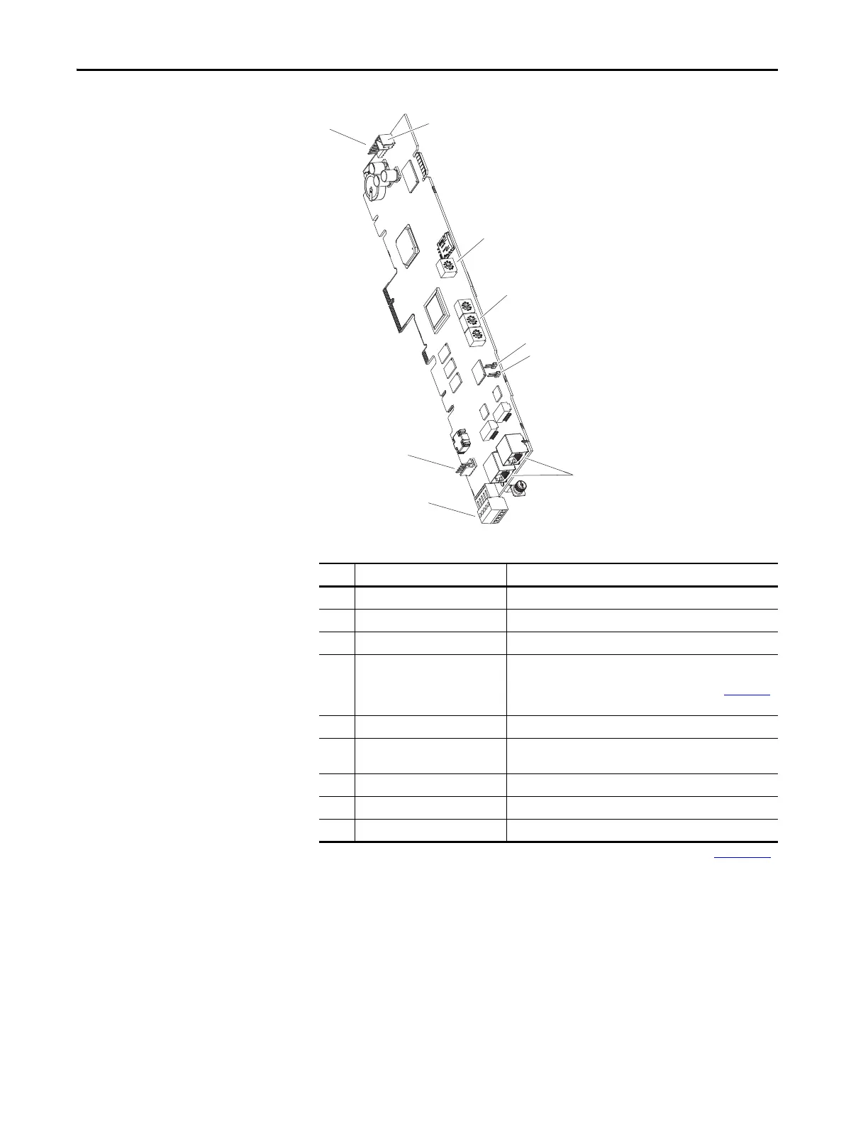
Main Control Board
Table 20 - Main Control Board Details
Item Name Description
1 HIM Connector DPI Port 01 (HIM Cradle) connection.
2 Fan Connector Power supply for internal cooling fan.
3 Control Selector Rotary switch for setting the programming mode.
4 Embedded EtherNet/IP
(1)
Address
Selectors
(1) Refer to the PowerFlex Drives with TotalFORCE Control Built-in EtherNet/IP Adapter User Manual, publication 750COM-UM009.
Rotary switches for setting lowest octet of EtherNet address (forces
address to 192.168.1.xxx). Refer to the PowerFlex Drives with
TotalFORCE Control Programming Manual, publication 750-PM100
for instructions on setting the IP address.
5 SAFETY Jumper Safety enable jumper. Removed when safety option is installed.
6 ENABLE Jumper Hardware enable jumper. TB1 becomes an Enable when this
jumper is removed.
7 Built-in EtherNet/IP
(1)
Connectors Network cable connections.
8 TB1 I/O terminal block.
9 DPI Port 2 Cable connection for handheld and remote HIM options.

 Loading...


