EasyManuals Logo
Home>Allen-Bradley>Controller>PowerFlex 700AFE

Allen-Bradley PowerFlex 700AFE Installation Instructions

Allen-Bradley PowerFlex 700AFE
192 pages
To Next Page IconTo Next Page
To Previous Page IconTo Previous Page
Page #87 background imageLoading...
Page #87 background image
Rockwell Automation Publication 750-IN100B-EN-P - July 2017 87
Mechanical and Electrical Installation Chapter 4
Join Enclosures
PowerFlex 755T products that ship in multiple sections must be connected
after they are located in their final positions. The enclosures are connected
together using the joining hardware provided.
Each of the three types of enclosure connections are made in the same way.
Entry wire bay to input bay
•Power bay to power bay
•Power bay to exit wire bay
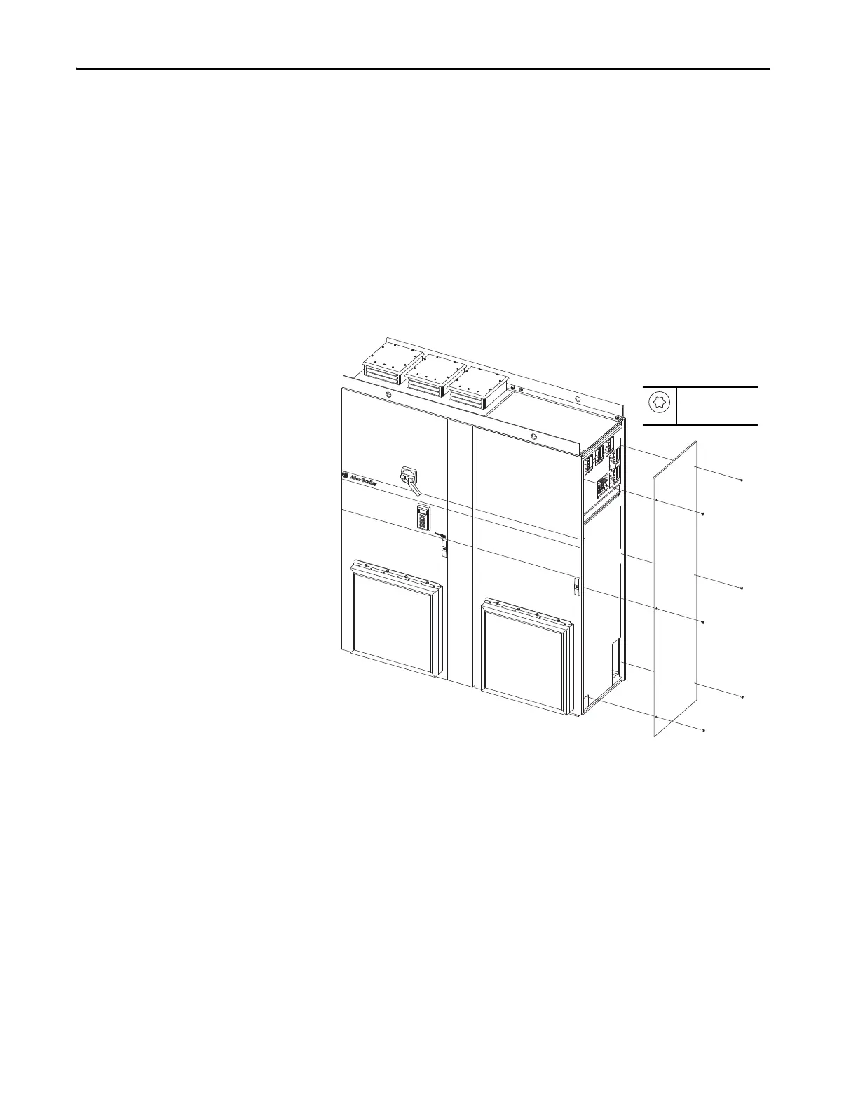
1. Remove the right exterior side sheet from the first power bay (Section 1
of n). Do this if you are joining enclosures. Reserve the side sheet to close
the end enclosure.
M6
T20
-

Table of Contents

Other manuals for Allen-Bradley PowerFlex 700AFE

Questions and Answers:

Question and Answer IconNeed help?

Do you have a question about the Allen-Bradley PowerFlex 700AFE and is the answer not in the manual?

Allen-Bradley PowerFlex 700AFE Specifications

General IconGeneral
BrandAllen-Bradley
ModelPowerFlex 700AFE
CategoryController
LanguageEnglish

Related product manuals