180 Rockwell Automation Publication 750-IN100B-EN-P - July 2017
Chapter 6 I/O Wiring
Motor Power Cables
For detailed information on 2090-Series flying-lead motor cables, refer to the
Kinetix Motion Accessories Specifications Technical Data, publication
GMC-TD004
.
Feedback Device Resolution
When using a PowerFlex 755 drive to control a permanent magnet motor, the
motor feedback device must have a resolution so that the number of pulses per
revolution (PPR) is an exponent of two.
For example: 512, 1024, 2048, 4096, 8192…524288, 1048576…
Motor Feedback Wiring
Examples
The Table 69 includes a list of motor, feedback device and cable wiring
examples.
IMPORTANT Only one linear feedback device can be connected to the option module.
Wire the device to either Channel X on TB1 or Channel Y on TB2.
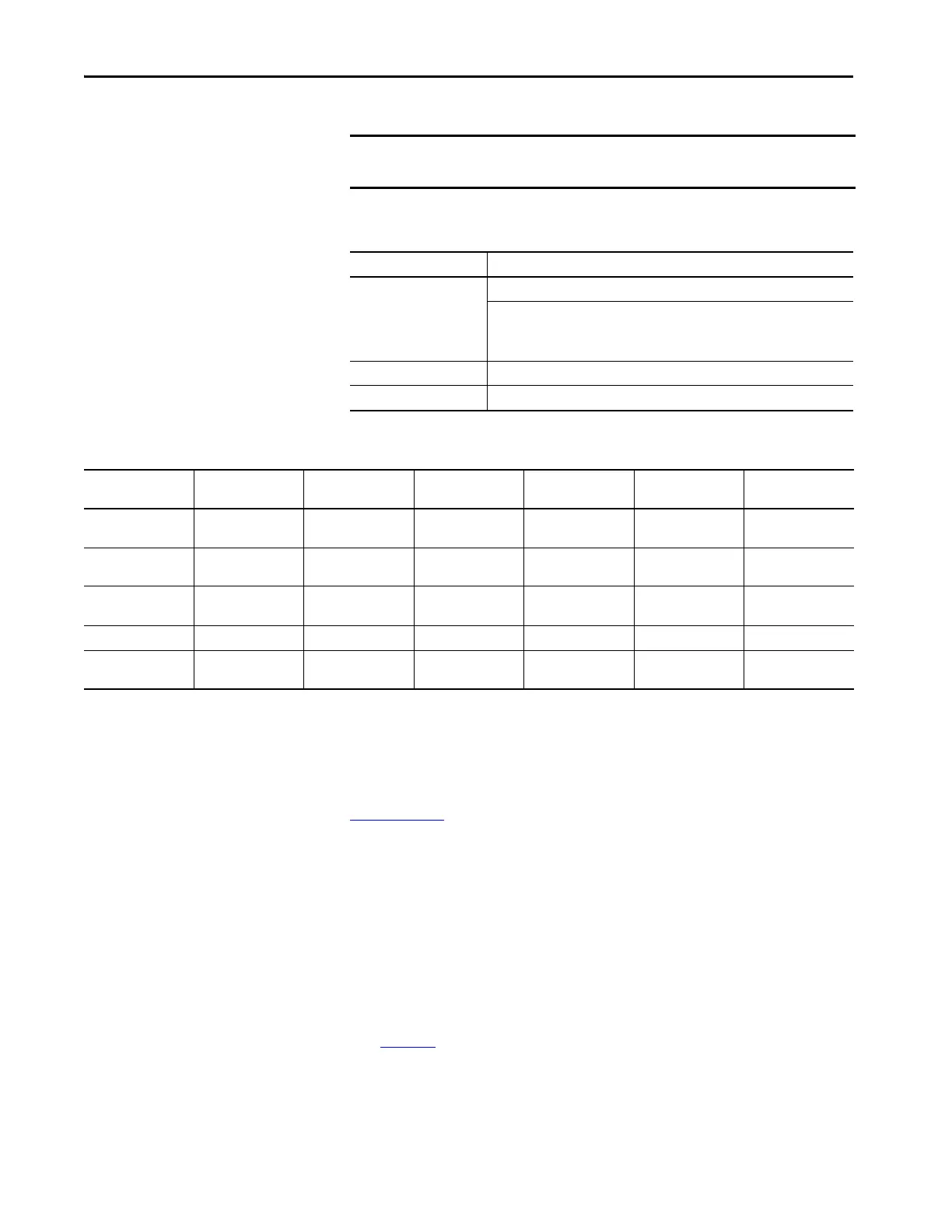
Table 67 - Universal Feedback Incremental AquadB Encoder
Consideration Description
Input Differential or Single Ended operation, Constant Current Sink operation ~10 mA
3.5V DC minimum to 7.5V DC maximum sourcing 10 mA
minimum high state voltage of 3.5V DC
maximum low state voltage of 0.4V DC
Maximum Cable Length 30 m (100 ft) @ 5V
Maximum Input Frequency 250 kHz
Table 68 - Supported Encoders
Consideration Heidenhain (EnDat) SSI Stegmann
(Hiperface)
BiSS Stahl (linear) Temposonics
(linear)
Encoder Voltage
Supply
5V @ 250 mA 10.5V @ 250 mA 10.5V @ 250 mA 10.5V @ 250 mA External Supplied 24V External Supplied 24V
High-Resolution
Signal
Sine/Cosine 1V P-P Sine/Cosine 1V P-P Sine/Cosine 1V P-P Sine/Cosine 1V P-P n/a n/a
Maximum Cable
Length
100 m 100 m 90 m 100 m 100 m 100 m
Update Rate
(1)
102.4 s 102.4 s 102.4 s 102.4 s 0.5/1.0/1.5/2.0 ms 0.5/1.0/1.5/2.0 ms
Maximum Input
Frequency
163.8 kHz 163.8 kHz 163.8 kHz 163.8 kHz n/a n/a
(1) The Universal Feedback Encoder Option Module will acquire the position with the update rates displayed.

 Loading...


