Rockwell Automation Publication 750-IN100B-EN-P - July 2017 187
I/O Wiring Chapter 6
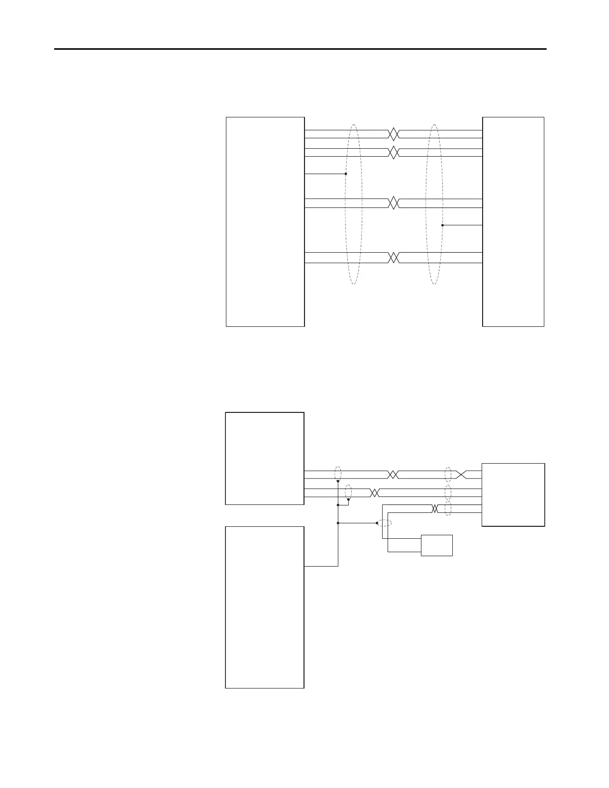
Figure 85 - Stegmann Rotary Encoder Connected via a Shielded, Twisted Pair Cable with a 12-
pin DIN Style Connector
Set Universal Feedback parameter 6 [FB0 Device Sel] or 36 [FB1 Device Sel]
to 2 ‘Hiperface SC.’
Figure 86 - Linear Sensor with MDI RG Connector or P Integral Cable
Set Universal Feedback parameter 6 [FB0 Device Sel] or 36 [FB1 Device Sel]
to 17 ‘LinStahl ChY’ or 19 ‘LinSSI ChY.’
Universal Feedback Option
Encoder TB
6
5
1
8
10
12
BK
PK
BU
RD
BN
WH
BN
WH
BK
PK
BU
RD
GN
GY
GN
GY
REFSIN
+SIN
REFCOS
+COS
DATA- (RS485)
DATA+ (RS485)
POWER COMMON
POWER
7
2
OVERALL SHIELD
9
11
4
3
N/C
N/C
N/C
-Sn
+Sn
-Cs
+Cs
IS
OS
-Xc
-Xd
+Xd
-Hf
+Hf
5c
+5
+Xc
12c
-A
A
-B
B
-Z
Z
+12
PK
GN
Universal Feedback Option
Module TB1
Universal Feedback Option
Module TB2
-Hm
+Hm
-R0
+R0
-R1
+R1
-Yc
-Yd
+Yd
+Yc
(+) Clock3
(-) Clock4
(-) Data1
(+) Data2
+24V DC
5
DC Ground
6
N/C7
Linear Sensor
TB
YE
GY
RD or BN
WH
PK
GN
YE
GY
RD or BN
WH
24V DC Power Supply
+ Power
- Common
-Sn
+Sn
-Cs
+Cs
IS
OS
-Xc
-Xd
+Xd
-Hf
+Hf
5c
+5
+Xc
12c
-A
A
-B
B
-Z

 Loading...


