132 Rockwell Automation Publication 750COM-UM009A-EN-P - May 2017
Appendix C Interface Parameters
363 Msg Flt Action
Message Fault Action
Sets the action that the interface and drive take when explicit messaging control (only
via PCCC or the CIP Assembly Object) is disrupted. When explicit messaging control is re-
established, the drive automatically receives the logic command, reference, and
datalinks over the network again.
‘Fault’ (0) – The response is a major fault. The drive stops modulating, the motor coasts
to a stop, and a fault reset is required to resume operation.
‘Stop’ (1) – The response is to stop in the way set by the active stop mode.
‘Zero Data’ (2) – The response is to continue operating, but to put zeros in the logic
command, reference, and datalinks.
‘Hold Last’ (3) – The response is to continue operating, and to use the last values in the
logic command, reference, and datalinks.
‘Send Flt Cfg’ (4) – The response is to continue operating, but to use the logic command
that is specified in parameter 364
[Flt Cfg Logic] and the reference that is specified in 365
[Flt Cfg Ref]. The drive also uses the values in parameters 370 [Flt Cfg DL 01]… 385 [Flt
Cfg DL 16] in the parameters consuming data from those datalinks.
Default:
Options:
0 = ‘Fault’
0 = ‘Fault’
1 = ‘Stop’
2 = ‘Zero Data’
3 = ‘Hold Last’
4 = ‘Send Flt Cfg’
RW 32-bit
Integer
0
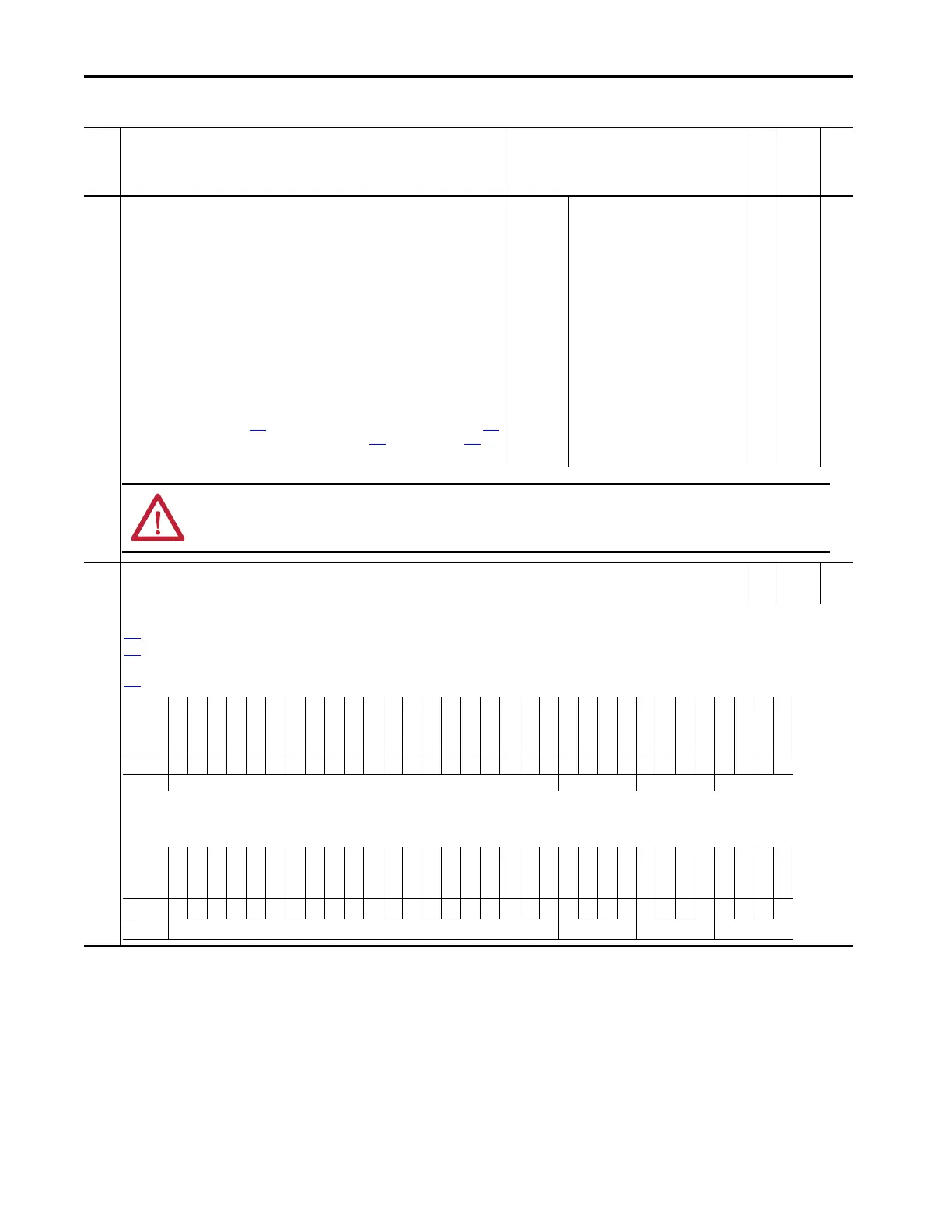
364 Flt Cfg Logic
Fault Configuration Logic
RW Bit 0
Set the logic command for the drive if any of the following is true:
360
[Comm Flt Action] is set to 4 ‘Send Flt Cfg’ and I/O communication are disrupted.
361
[Idle Flt Action] is set to 4 ‘Send Flt Cfg’ and the controller leaves the run mode.
362 [Peer Flt Action] is set to 4 ‘Send Flt Cfg’ and Peer I/O communication are disrupted.
363 [Msg Flt Action] is set to 4 ‘Send Flt Cfg’ and Explicit Messaging for drive control is disrupted.
Note: The first bit table is for systems that contain both an inverter and a converter or only an inverter. The second bit table is for systems that contain ONLY a converter.
Table 25 - Port 0: Parameter List (continued)
No. Display Name
Extended Name
Description
Values
Read-Write
Data Type
Parameter 30
[Access Level]
ATTENTION: Take precautions to help maintain that the setting of this parameter does not create a risk of injury or equipment damage. When
commissioning the drive, verify that your system responds correctly to various situations (for example, a disconnected cable).
Options
Reserved
Reserved
Reserved
Reserved
Reserved
Reserved
Reserved
Reserved
Reserved
Reserved
Reserved
Reserved
Jog 2
Run
Climit Stop
Coast Stop
Reserved
SpdRef Sel 2
SpdRef Sel 1
SpdRef Sel 0
Decel Time 2
Decel Time 1
Accel Time 2
Accel Time1
Reserved
Manual
Reverse
Forward
Clear Faults
Jog 1
Start
Stop
Default00000000000000000000000000000000
Bit 313029282726252423222120191817161514131211109876543210
Options
Reserved
Reserved
Reserved
Reserved
Reserved
Reserved
Reserved
Reserved
Reserved
Reserved
Reserved
Reserved
Reserved
Run
Reserved
Reserved
Reserved
Reserved
Reserved
Reserved
Reserved
Reserved
Reserved
Reserved
Reserved
Reserved
Reserved
Reserved
Clear Faults
Reserved
Start
Stop
Default00000000000000000000000000000000
Bit 313029282726252423222120191817161514131211109876543210

 Loading...


