64 Rockwell Automation Publication 20C-PM001F-EN-P - March 2012
Chapter 3 Troubleshooting
Fault and Alarm Descriptions
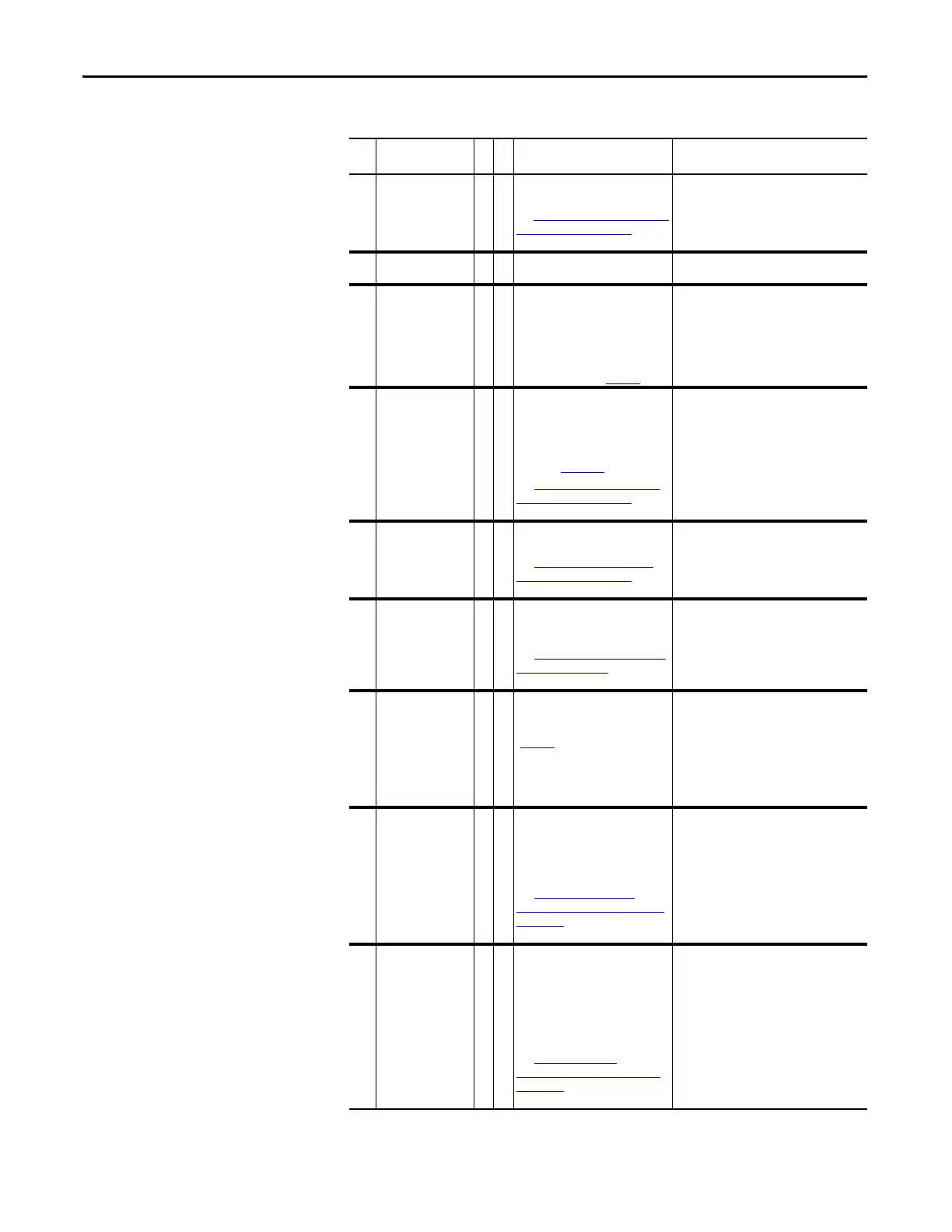
Table 1 - Fault/Alarm Types, Descriptions and Actions
No. Name
Fault
Alarm
Description Action (if applicable)
1 PrechargeActv 1 The drive received a start command
while in the DC bus precharge state.
See Table 3, “
Precharge Active Fault
(F1) Subcodes,” on page 71 for
more information on this fault.
–
2 Auxiliary In 1 The auxiliary input interlock is
open.
Check all remote wiring.
3Power Loss 1,
3
1 The DC bus voltage remained below
the value set in parameter 186
[Power Loss Volts] for longer than
the time specified in parameter 185
[Power Loss Time]. You can enable/
disable this fault with parameter
238 [Fault Config 1] (page 42
).
Monitor the incoming AC line for low voltage
or line power interruption.
4UnderVoltage 1,
3
1 The DC bus voltage fell below the
minimum value of 333V for 400/
480V drives and 461V for 600/ 690V
drives. You can enable/disable this
fault with parameter 238 [Fault
Config 1] (page 2-42
).
See Table 4, “Under Voltage Fault
(F4) Subcodes,” on page 71 for
more information on this fault.
Monitor the incoming AC line for low voltage
or power interruption.
5 OverVoltage 1 The DC bus voltage exceeded the
maximum value.
See Table 5, “Over Voltage Fault
(F5) Subcodes,” on page 71 for
more information on this fault.
Monitor the AC line for high line voltage or
transient conditions. Bus overvoltage can
also be caused by motor regeneration.
Extend the decel time or install a dynamic
brake option.
6 Motor Stall 2 The motor is operating at high
current and low frequency and is
not accelerating.
See Table 6, “
Motor Stall Fault (F6)
Subcode,” on page 71 for more
information on this fault.
1. Run an Autotune.
2. Reduce the Load.
7 MotorOverload 1,
3
Internal electronic overload trip.
You can enable/disable this fault
with parameter 238 [Fault Config 1]
(page 42
).
1. Run an Autotune.
2. Verify the settings of parameters 48
[Motor OL Factor] and 47 [Motor OL
Hertz].
3. Reduce the load so that the drive output
current does not exceed the current set
by the value in parameter 42 [Motor NP
FLA].
8 HeatsinkOvrTp 2 1 The heatsink temperature has
exceeded the maximum allowable
value.
85 degrees C = Alarm
90 degrees C = Fault
See Table 7, “
Heatsink Over
Temperature Fault (F8) Subcodes,”
on page 71 for more information on
this fault.
1. Verify that the maximum ambient
temperature has not been exceeded.
2. Check the fans (including the ASIC board
on frame 10 and higher drives).
3. Check for an excess load.
4. Check the carrier frequency.
9 IGBT OverTemp 1 The output transistors have
exceeded their maximum operating
temperature due to an excessive
load.
Note: IGBT Overtemp = Drive
Overload (Software), not
adjustable.
See Table 8, “IGBT Over
Temperature Fault (F9) Subcode,”
on page 72 for more information on
this fault.
1. Verify that the maximum ambient
temperature has not been exceeded.
2. Check the fan(s).
3. Check for an excess load.

 Loading...


