Rockwell Automation Publication 20C-PM001F-EN-P - March 2012 91
Application Notes Appendix B
Overspeed
Overspeed Limit is a user programmable value that allows operation at maximum
speed, but also provides an “overspeed band” that will allow a speed regulator
such as slip compensation to increase the output frequency above maximum
speed in order to maintain maximum motor speed.
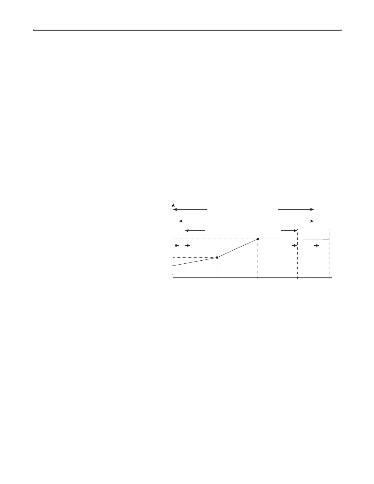
The figure below illustrates a typical Custom V/Hz profile. Minimum Speed is
entered in Hertz and determines the lower speed reference limit during normal
operation. Maximum Speed is entered in Hertz and determines the upper speed
reference limit. The two “Speed” parameters only limit the speed reference and
not the output frequency.
The actual output frequency at maximum speed reference is the sum of the speed
reference plus “speed adder” components from functions such as slip
compensation.
The Overspeed Limit is entered in Hertz and added to Maximum Speed and the
sum of the two (Speed Limit) limit the output frequency. This sum (Speed
Limit) must is compared to Maximum Frequency and an alarm is initiated which
prevents operation if the Speed Limit exceeds Maximum Frequency.
Power Loss Ride Through
When AC input power is lost, energy is being supplied to the motor from the
DC bus capacitors. The energy from the capacitors is not being replaced (via the
AC line), thus, the DC bus voltage will fall rapidly. The drive must detect this fall
and react according to the way it is programmed.
There are three possible methods of dealing with low bus voltages:
1. “Coast” – Disable the transistors and allow the motor to coast.
2. “Decel” – Decelerate the motor at just the correct rate so that the energy
absorbed from the mechanical load balances the losses.
3. “Continue” – Allow the drive to power the motor down to the
undervoltage trip level.
Two parameters display DC bus voltage:
Allowable Output Frequency Range
Bus Regulation or Current Limit
Voltage
Frequency
Allowable Output Frequency Range
Normal Operation
Allowable Reference Frequency Range
Frequency Trim due to
Speed Control Mode
Motor Volts
Break Volts
Start Boost
0Min
Speed
Motor
Hz
Max
Speed
Output
Freq Limit
Max
Freq
Break
Frequency
Overspeed
Limit