COMPONENTS
Vector™ H Serie s ▪ S ervice M an ual ▪ MN-4 6 543 ▪ R ev 01 ▪ 11/ 1 9
34
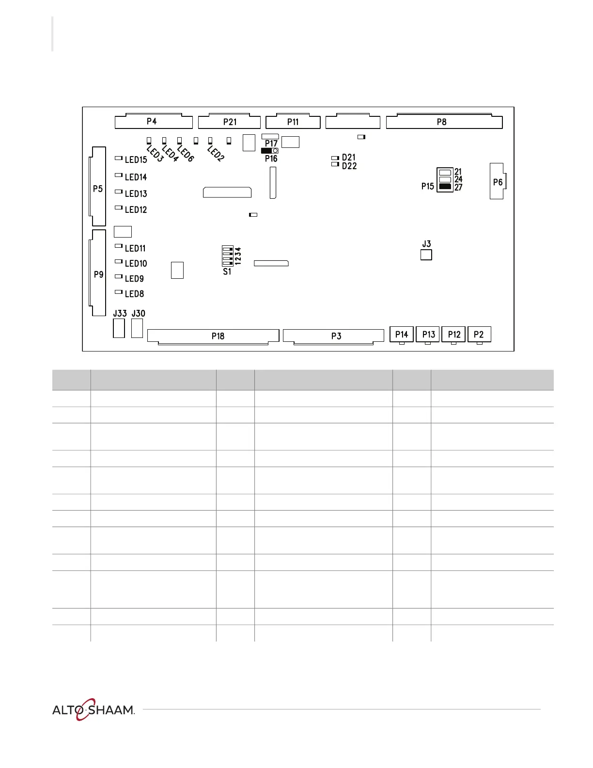
Control Board (CB)
VMC-PHD-001947
TELCO VFD OFF
SIEMENS VFD ON
ONÍ
V
V
V
Ref. Description Ref. Description Ref. Description
P2 Drive 1 communication P16 Jumper LED 9 Chamber 2 call for heat
P3 Input signals P17 Not used LED 10 Chamber 3 call for heat
P4 Door handle lights
(if equipped)
P18 Input from chamber combine
switches (F Series only)
LED 11 Chamber 4 call for heat
P5 Lights P21 Output to blower/fan relay RL1 LED 12 Chamber 1 light
P6 Input from 12VDC power
supply
J3 Speaker LED 13 Chamber 2 light
P8 Thermocouple inputs J30 AC input from the transformer LED 14 Chamber 3 light
P9 Heater control signal to SSRs J33 AC input from the transformer LED 15 Chamber 4 light
P11 or
P10
Communication to UI board LED 2 Cooling fan power D21 RS485 communication
P12 Drive 2 communication LED 3 Door handle lights (if equipped) D22 RS485 communication
P13 Drive 3 communication LED 4 Door handle lights
(if equipped)
S1 Chamber VFD selection
Telco VFD set to OFF
Siemens VFD set to ON
P14 Drive 4 communication LED 6 Door handle lights (if equipped) — —
P15 Jumper LED 8 Chamber 1 call for heat — —
 Loading...