TROUBLESHOOTING
Ve ct or™ H Se ries ▪ S ervice Ma nual ▪ MN -4 6 54 3 ▪ R ev 01 ▪ 11/ 19
91
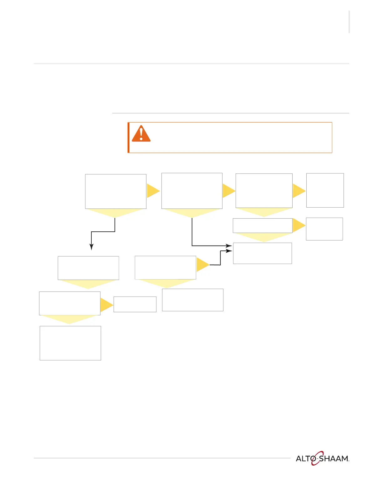
All Chamber Blower Fans do not Operate
Before you begin ▪ Locate the circuit breakers and reset any tripped circuit breaker as required.
▪ Remove the service panel.
▪ Navigate to the service screen, touch the blower test icon, set the blower speed
to 100%, touch the check mark.
WARNING: Electric shock and arc flash hazard.
Use caution when measuring line voltage.
Wear Personal Protective Equipment (PPE).
Is LED 2 on the control
board illuminated
Measure DC voltage
across the coil terminals of
relay RL 2.
Is the 12VDC present?
No
No
Yes
Are the common and
normally open contacts of
RL 2 closed?
Inspect the wires,
terminal blocks and
connectors. Repair any
damaged wires or
connectors.
Are LEDs 1 and 2 on the
user interface board and
LEDs D21 and D22 on the
control board flashing?
Replace the
cable and retest.
Replace the
interface board
and retest.
Is LED 2 (TX) on the
interface board blinking?
Replace the Control
board and retest.
Replace relay RL 2.
No
NoNoNo
Yes Yes
Yes
Yes
Yes
Yes
VMC-TS-008606
Ohm out the
communication cable
between the control board
and the interface board.
Does the cable ohm out ok?
Inspect the wires and
connectors. Repair any
damaged wires or
connectors.
Measure DC voltage across
the control board connector
P21 pins 2 and 3.
Is the 12VDC present?
 Loading...