 Loading...
Do you have a question about the Asus M2N-L and is the answer not in the manual?
| ECC | Yes |
|---|---|
| Number of memory slots | 4 |
| Maximum internal memory | 8 GB |
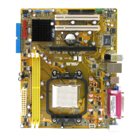
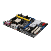
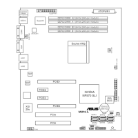
| Processor socket | Socket AM2 |
| Processor manufacturer | AMD |
| USB 2.0 connectors | 1 |
| Number of SATA connectors | 6 |
| Manageability features | ASWM 2.0 |
| Controller interface type | Serial ATA I/II |
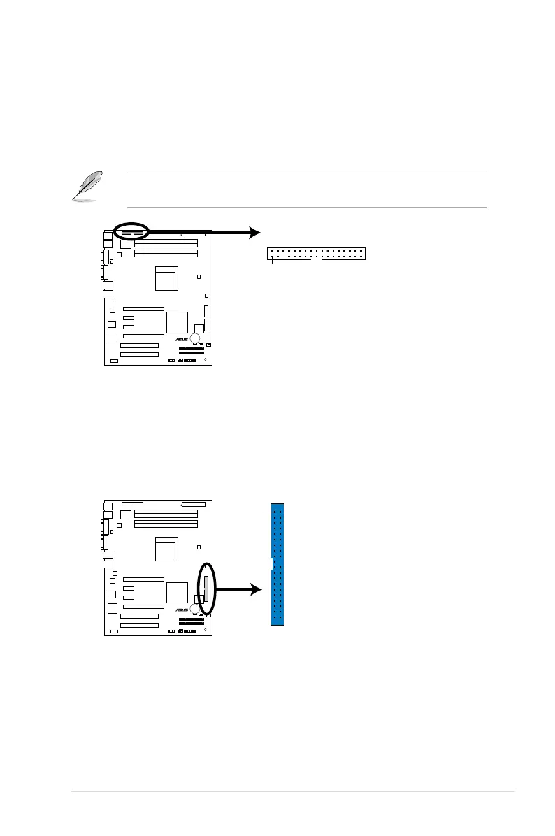
| Controller 2nd interface type | UltraATA-100/133 |
| USB 2.0 ports quantity | 2 |
| Motherboard form factor | ATX |
| Maximum graphics card memory | 32 MB |
| Networking features | Dual Gigabit Ethernet |
| Storage temperature (T-T) | -20 - 70 °C |
| Operating temperature (T-T) | 10 - 35 °C |
| RAID levels | 0, 1, 0+1, JBOD |