2-24 Chapter 2: Hardware information
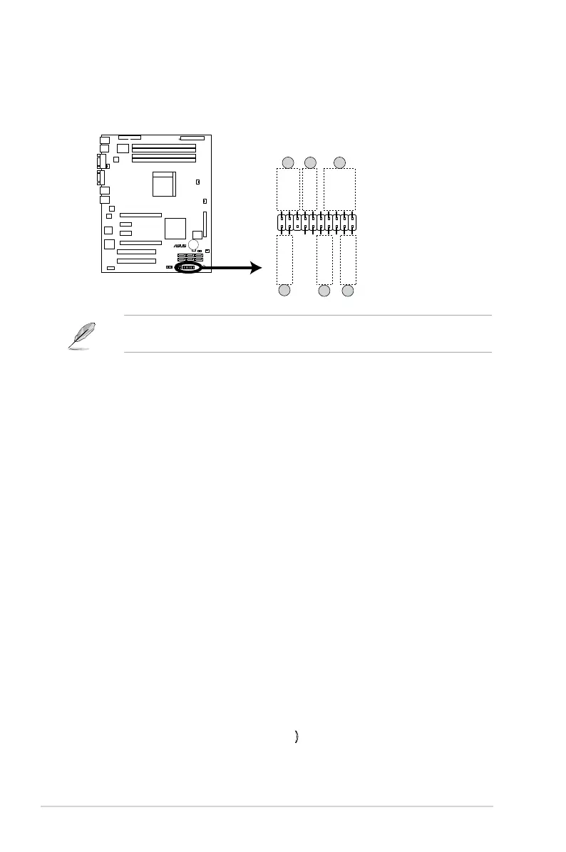
8. System panel connector (20-1pin PANEL1)
This connector supports several chassis-mounted functions.
The system panel connector is color-coded for easy connection. Refer to the
connector description below for details.
1. System power LED (Green 3-pin POWERLED)
This 3-pin connector is for the system power LED. Connect the chassis
power LED cable to this connector. The system power LED lights up when
you turn on the system power, and blinks when the system is in sleep mode.
2.
Message LED (Brown 2-pin MLED)
This 2-pin connector is for the message LED cable that connects to the
front message LED. The message LED is controlled by Hardware monitor to
indicate an abnormal event occurance.
3. System warning speaker (Orange 4-pin SPKROUT)
This 4-pin connector is for the chassis-mounted system warning speaker. The
speaker allows you to hear system beeps and warnings.
4. Hard disk drive activity (Red 2-pin HDDLED)
This 2-pin connector is for the HDD Activity LED. Connect the HDD Activity
LED cable to this connector. The IDE LED lights up or ashes when data is
read from or written to the HDD.
If an optional SATA add-in card is installed, the read or write activities of any
device connected to the SATA add-in card causes this LED to light up.
5. Power/Soft-off button (Yellow 2-pin POWERBTN)
This connector is for the system power button. Pressing the power button
turns the system ON or puts the system in SLEEP or SOFT-OFF mode
depending on the BIOS settings. Pressing the power switch for more than
four seconds while the system is ON turns the system OFF.
6. Reset button (Blue 2-pin RESETBTN)
This 2-pin connector is for the chassis-mounted reset button for system
reboot without turning off the system power.
M2N-L
®
M2N-L System Panel Connector
PANEL1
MLED-GND
NCPOWERBTN#
+5VGND
GNDNC
POWERLED+HDLED+
GNDHDLED-
POWERLED-
MLED+NMIBTN#
GNDRESETBTN#
SPKROUTGND
321
4
5 6
 Loading...