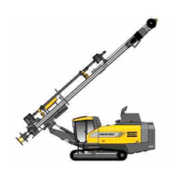
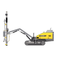
FlexiROC T35 R/T40 R 2 General
13 No: 3171473547.1 en
The emergency stop buttons/cables are connected in series with the diesel engine cut-out
system. As soon as an emergency stop button/cable is activated, the diesel engine will be
stopped immediately. Reset the emergency stop buttons before restarting the engine. The
engine cannot be started while one of the emergency stops is still activated.
For further details, see separate wiring diagram.
For details of the diesel engine, see separate diesel engine instructions.
2.4.7 Hydraulic system
The principal components of the hydraulic system comprise oil cooler, hydraulic oil tank,
valves, hoses and four hydraulic pumps.
The four hydraulic pumps create hydraulic pressure in order to control the different func-
tions. The table below indicates which hydraulic pump controls which function.
Pump no. Description
1 Drill feed, rapid feed, percussion, tramming
2 Rotation, preheating
3 Dust collector (DCT), winch, boom positioning
4 Cooler motor
Table1: Description of hydraulic pump function
The hydraulic oil tank is located on the right-hand side of the drill rig.
The combination cooler is located in the centre of the drill rig.
(For further details, see separate hydraulic system diagram)
 Loading...