English
7
What to check after wiring
Once actuator wiring is completed, please check the following:
1. Make sure that power supply voltage matches information on
the sticker on the side of the actuator.
2. Check that all connectors or cable glands are correctly
tightened.
3. Manually drive the valve to a mid-travel position.
4. Electrically operate counter-clockwise rotation and check that
the motor rotates in the right direction.
5. Manually press on the counter-clockwise travel limit switch
then the motor should stop.
6. Repeat steps 4 and 5 for clockwise direction.
• If any fault is detected at this stage, please check again the
whole wiring.
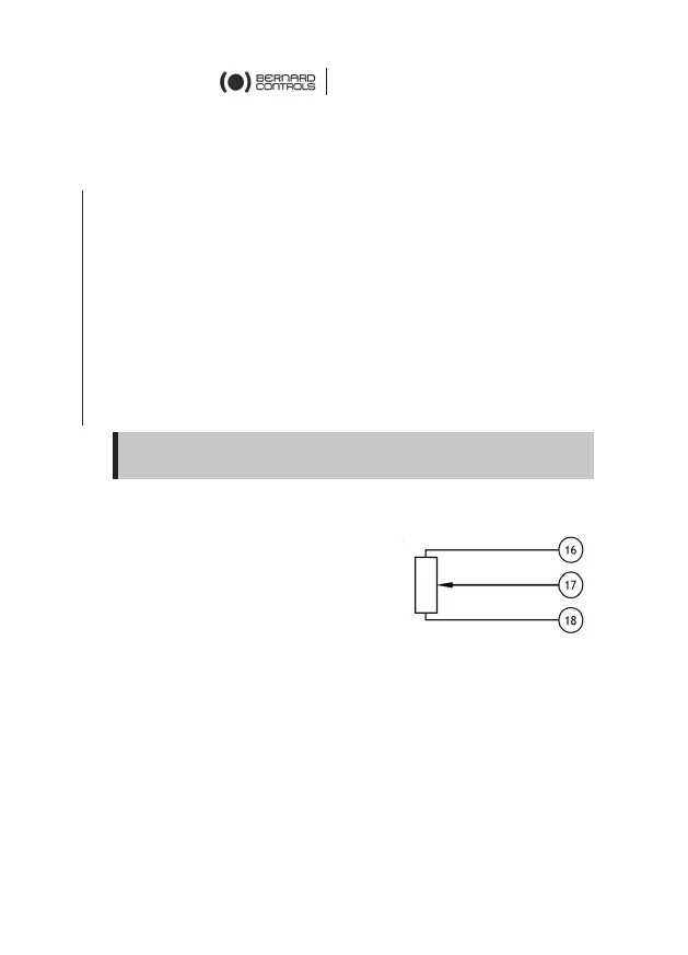
Position feedback potentiometer (OPTION)
The potentiometer used for actuator
position feedback is driven by the travel
cam block system.
For clockwise closing:
• 0% position indicates a closed valve
• 100% position indicates an open valve.
Resistance value is measured between 16 and 17 terminals.
 Loading...