Electrical connection
Compress Hybrid 3400i AW – 6721861825 (2023/08)
20
6.1 Connecting the device
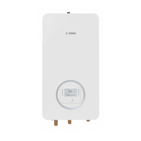
Due to the IP rating IPX1D, the appliance must not be installed in
protection zones 1 and 2.
Fig. 28 Protection zones
[1] Protection zone 1, directly above the bath
[2] Protection zone 2, within a radius of 60 cm from the bath/shower
6.2 Routing cables
NOTICE
Material damage due to damaged cables!
System damage may occur if cables are installed incorrectly or next to
hot system components.
▶ Make sure cables are not pinched.
▶ Route all cables through cable feeds.
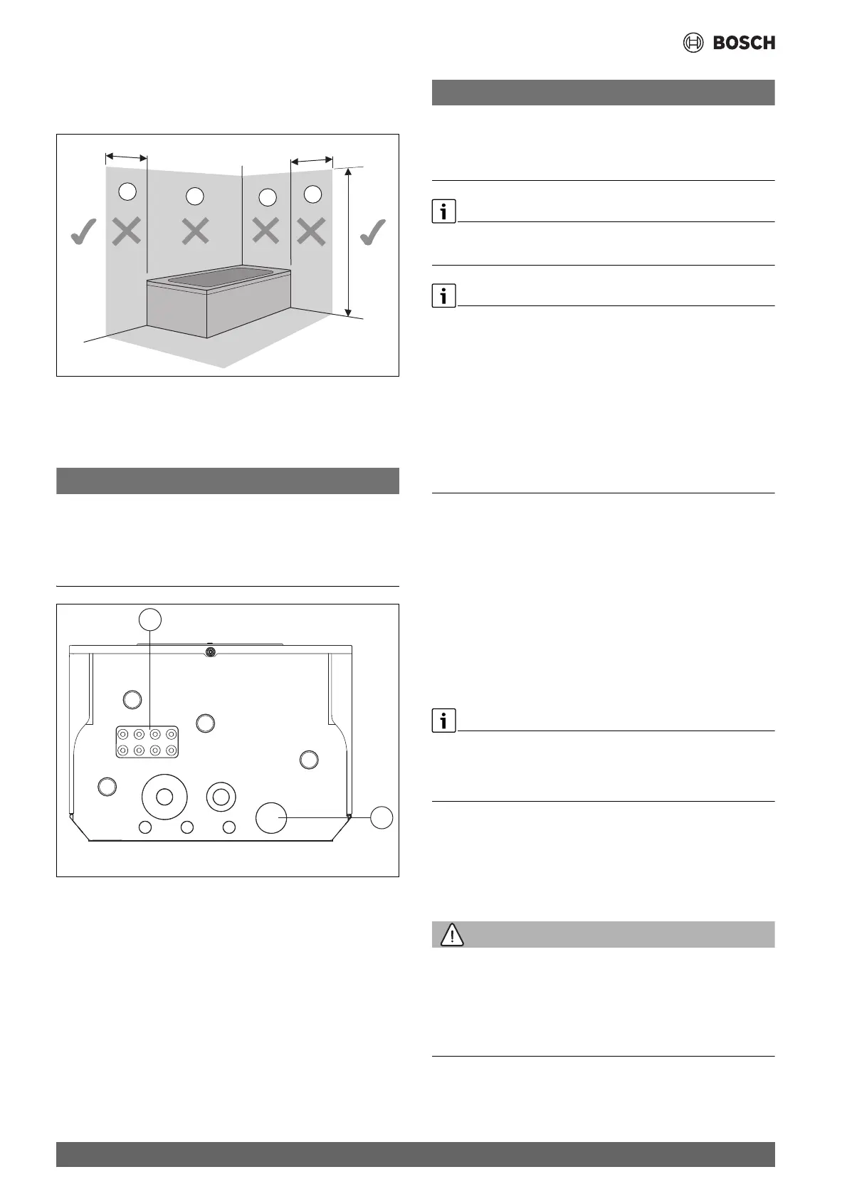
Fig. 29 Cable feeds
[1] Cable feed for sensor, CAN BUS and EMS bus
[2] Cable feed for mains power supply (230 V)
NOTICE
Material damage due to induced overvoltage!
Incorrectly installed cables can lead to induced overvoltages which can
cause the control unit to malfunction or be damaged.
▶ Route 230 V cables and extra-low voltage cables separately.
EMS-BUS and CAN-BUS are not compatible.
▶ Do not connect EMS-BUS units to CAN-BUS units.
It must be possible to safely interrupt the power supply to the appliance.
▶ Install a separate safety switch that completely de-energizes the
indoor unit.
▶ For a separate power supply, a safety switch is required for each
supply line.
▶ In case a fixed appliance is not equipped with a power cable and plug
or other means to shutdowwn from the power supply that has a
contact opening width at each pole according to the conditions of
overvoltage category III for full disconnection:
Install the respective disconnecting device in the fixed electrical
installation in accordance with the installation regulations.
▶ Select the appropriate conductor cross-sections and cable types for
the respective fuse protection and routing method.
▶ Mount the enclosed terminals on the installation PCB.
▶ Connect the unit as shown in the connection diagram. No additional
consumers may be connected.
▶ When changing the PCB, note the colour coding.
When extending temperature sensor cables, use the following conductor
diameters:
• up to 20 m long cable: 0.75 to 1.50 mm
2
• up to 30 m long cable: 1.0 to 1.50 mm
2
6.3 Connecting the power supply
A cable of the type H05V2V2 F, 3x1.5 mm
2
which is 2.5 m in length is
connected as standard to the mains power supply terminal (Fig. 30).
Alternatively an on-site connection can be established using a suitable
cable.
▶ Remove the cover (Chapter 5.3.1, page 10).
▶ Feed connecting lead through the cable feed [2] into the appliance.
▶ Establish a permanent connection to the mains power supply in
accordance with the locally applicable regulations.
▶ Connect the mains power supply via the mains power supply terminal
on the retaining plate (Fig. 30, [2]).
WARNING
Danger to life from electrical shock in the event of incorrectly
connected cables!
Ensure correct polarity of the N and L cables.
▶ Establish clamp connection correctly.
▶ Fully tighten clamp connection.
▶ Do not use an adapter plug (push fit connections).
▶ Make sure the potentiometer setting is correct for hybrid application
(P=3 and A=0) as shown in Fig. 30, [1]. If necessary, turn the
direction arrow to the corresponding position with a screwdriver.
0 010 007 511-001
225 cm
2
2
1
1
60 cm
60 cm
 Loading...