Preparing for installation
9
Compress Hybrid 3400i AW – 6721861825 (2023/08)
4.5 Installing the pressure-relief valve
▶ Install the pressure-relief valve in the flow outside the indoor unit.
▶ Ensure the pressure relief valve drain pip is not exposed to potential
freezing. Insulation may be required.
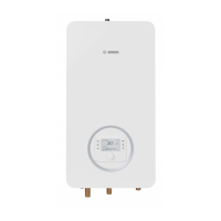
Fig. 8 Assembly of the pressure-relief valve
[1] Water pressure relief valve
[2] O-ring
[3] Pressure-relief valve connector pipe
[4] Retaining spring
[5] Gasket
4.6 Installing the heating pump (optional)
(Chapter 12.2, page 35)
Whether or not it is necessary to install a heating pump depends on the
configuration of the heating system and the amount of system
resistance.
▶ Select the heating pump based on the required pump flow rate and
pressure loss.
▶ Observe the minimum volumetric flow rate (Tab. 13, page 34).
▶ Install the bypass [1] between the flow [2] and return [3] (Fig. 9),
to hydraulically uncouple the heating pump from the heating circuit.
Observe the prescribed dimensions and clearances during assembly
(Tab. 8).
Table 8 Pipe diameter and bypass lengths
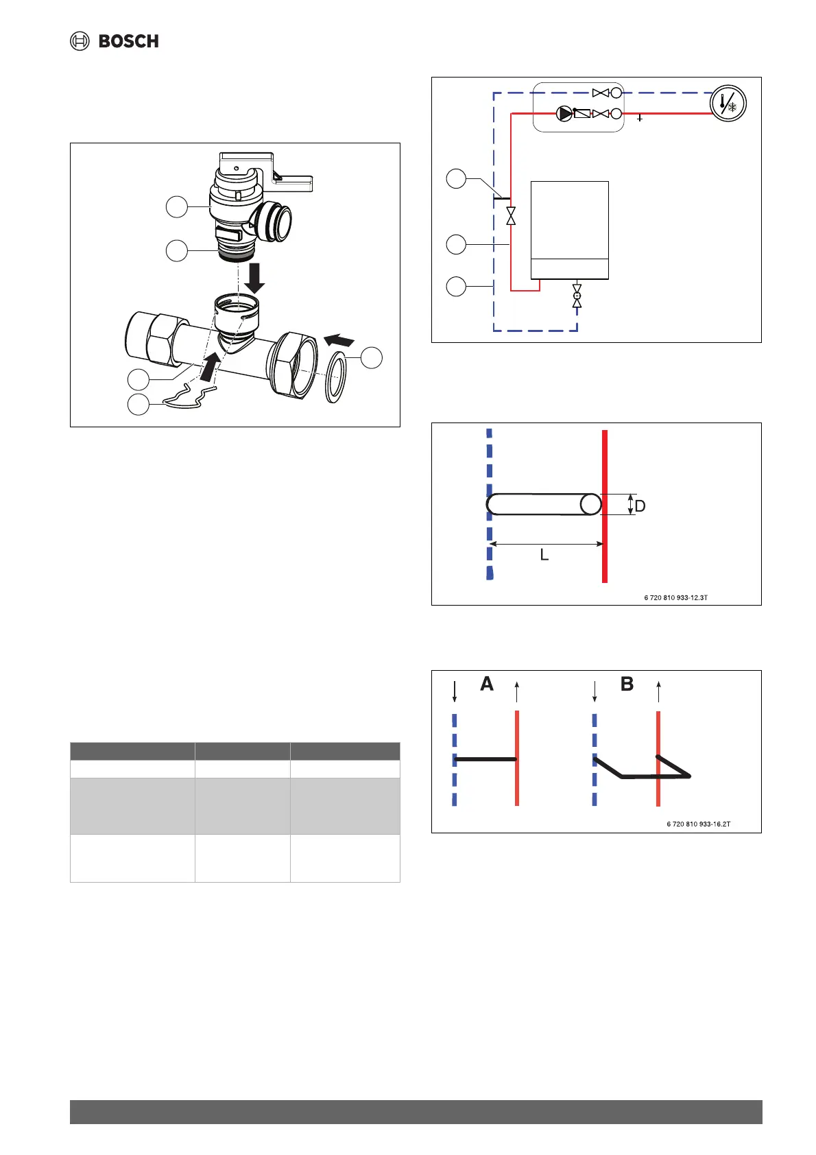
Fig. 9 Indoor unit with heating circuit and bypass
[1] By-pass
[2] Flow
[3] Return
Fig. 10 Detailed view of bypass
[L] Minimum bypass length
[D] Pipe diameter
Fig. 11 By-pass
[A] Bypass, straight design
[B] Bypass, U-shaped design (total length including the elbow)
4.7 Maximum sensor
In some countries a high limit safety cut-out is required in underfloor
heating circuits.
▶ Observe country-specific regulations.
▶ Establish connection as described in chapter 6.
Dimensions/clearances Unit Value
External diameter D mm 22
Minimum bypass length L
• Straight version A
• U-shaped version B
mm
mm
200
100
Maximum clearance
between bypass and
indoor unit
m1.5
 Loading...