Appendix
Compress Hybrid 3400i AW – 6721861825 (2023/08)
40
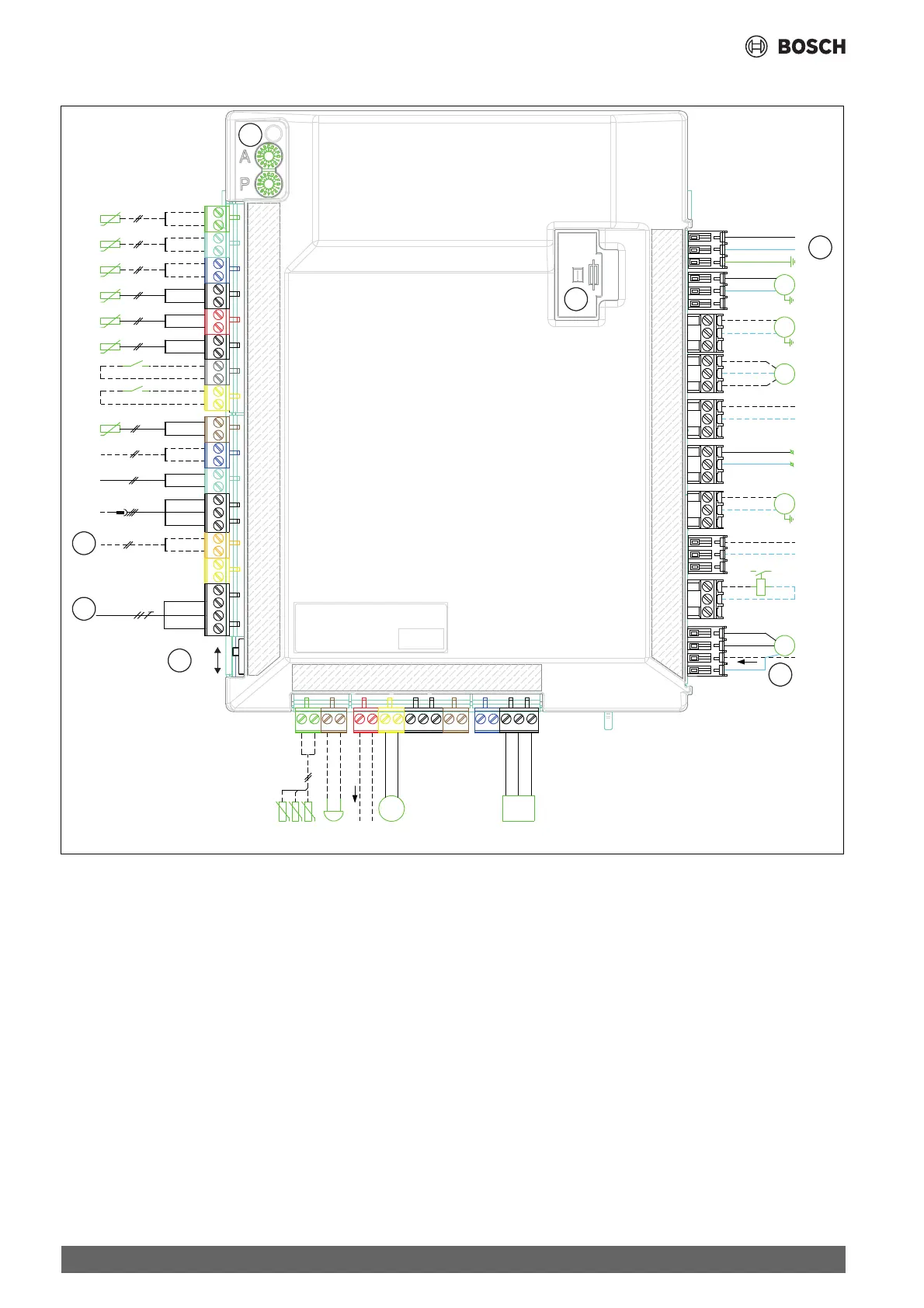
12.4 Installer module
Fig. 48 Connection diagram of installer module
PC0
PC1
PW2
PK2
EA1
6
EM0
EW1
MMM
VW1
M
M
M
0-10V
T1
TW1
TC1
I1
TC0
T0
I4
TC3
TR3
HMI bus
EMS bus
Service Tools
BB tool
3
2
Off
On
4
JR1
PC0
PWM
MD1
Buzzer
1
7
EM0
VM0
FM0
5
0010036535-003
CAN-BUS
HC
HC
[1] A and P encoders
[2] Connectivity gateway (accessory)
[3] CAN-BUS to outdoor unit
[4] CAN termination switch
[5] Alarm of the external auxiliary heater (230V ~ input)
[6] Power supply, 230 V~
[7] Fuse 5x20, 6.3A time lag
[T0] Heating circuit flow temperature sensor
[T1] Outside temperature sensor
[TW1] DHW temperature sensor
[TC0] Return temperature sensor
[TC1] Flow temperature sensor
[TC3] Condenser temperature sensor
[I1] External input 1
[I4] External input 4
[TR3] Refrigerant liquid temperature
[MD1]Condensation sensor(s)
[Buzzer] Alarm buzzer (accessory)
[EM0] Request for external auxiliary heater (on/off)
[PC0 PWM]PWM signal, primary circulation pump
[JR1] Refrigerant gas pressure sensor
[VM0] Open/closed mixing valve
[EW1]Request for external auxiliary heater in DHW cylinder
[PW2]DHW circulation pump
[EA1] Heating cable (outdoor unit accessory)
[PK2] Relay output, cooling mode, 230 V~
[VW1]DHW 3-way diverter valve
[PC1] Heating circulation pump
[PC0] Primary circulation pump
 Loading...