Electrical connection
Compress Hybrid 3400i AW – 6721861825 (2023/08)
22
6.7 External booster heater (uncommon in UK market)
6.7.1 Connect the actuator of the external booster heater (e.g.
floor standing boiler)
The external booster heater can be connected in two different ways:
Power control via 0-10V output:
▶ Connect the external booster heater to the installer module at
terminal EM0 0-10 V ( Chapter 12.4, page 40 [29]).
With some heat generators, an additional module (e.g. MU100,
accessory) must be installed to provide a 0-10 V input.
– or –
On/Off control (volt free output):
A relay contact is provided at connection terminal [2], which is potential-
free when volt free. The switching contact (open/closed) can be
evaluated by an external booster heater via a signal line. For this
purpose, a low or extra-low voltage must be fed from the external booster
heater via the connection terminal [2].
Contact voltage: 0...230 V
Contact current: 0...0.1 A
▶ Route the control cable of type H05V2V2 F, 2x0.75 mm
2
[4] from
the external booster heater through a free cable feed in the bottom
panel (Fig. 29) to terminal [2].
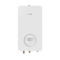
▶ Connect the stripped ends of the cable to the terminal of the relay box
and lock the terminal ( Fig. 32 [2], [1] and Chapter 12.4, page
40).
▶ Secure the cable [4] via the strain relief [3].
When there is heat demand from the external booster heater, the
relay box establishes a zero volt connection between the contacts of
the terminal.
Fig. 32 Terminal on the relay box
[1] Relay box
[2] External booster heater control cable terminal (volt free)
[3] Strain relief
[4] External booster heater control cable
The mixing valve does not open immediately after the external booster
heater is activated. A delay time for opening the mixing valve can be set
at the control unit (Chapter 8.5.2).
Always set the delay time to 0 min for hybrid applications.
Possible cycling of the boiler is a normal procedure. A buffer cylinder can
be installed if problems occur with the external auxiliary heater because
the elapsed time is too short.
▶ For more information, contact the manufacturer of the external
booster heater.
6.7.2 Connect the alarm signal for the external booster heater
Connection of the alarm signal depends on whether or not the external
booster heater has a 230 V alarm output.
If the external booster heater is equipped with a 230 V alarm output:
▶ Remove jumper between terminal 61 and 64
( Chapter 12.4, page 40).
▶ Connect 230 V alarm signal (AC) as shown in figure 33 to the
installer module at terminal FM0 ( Chapter 12.4, page 40 [26]).
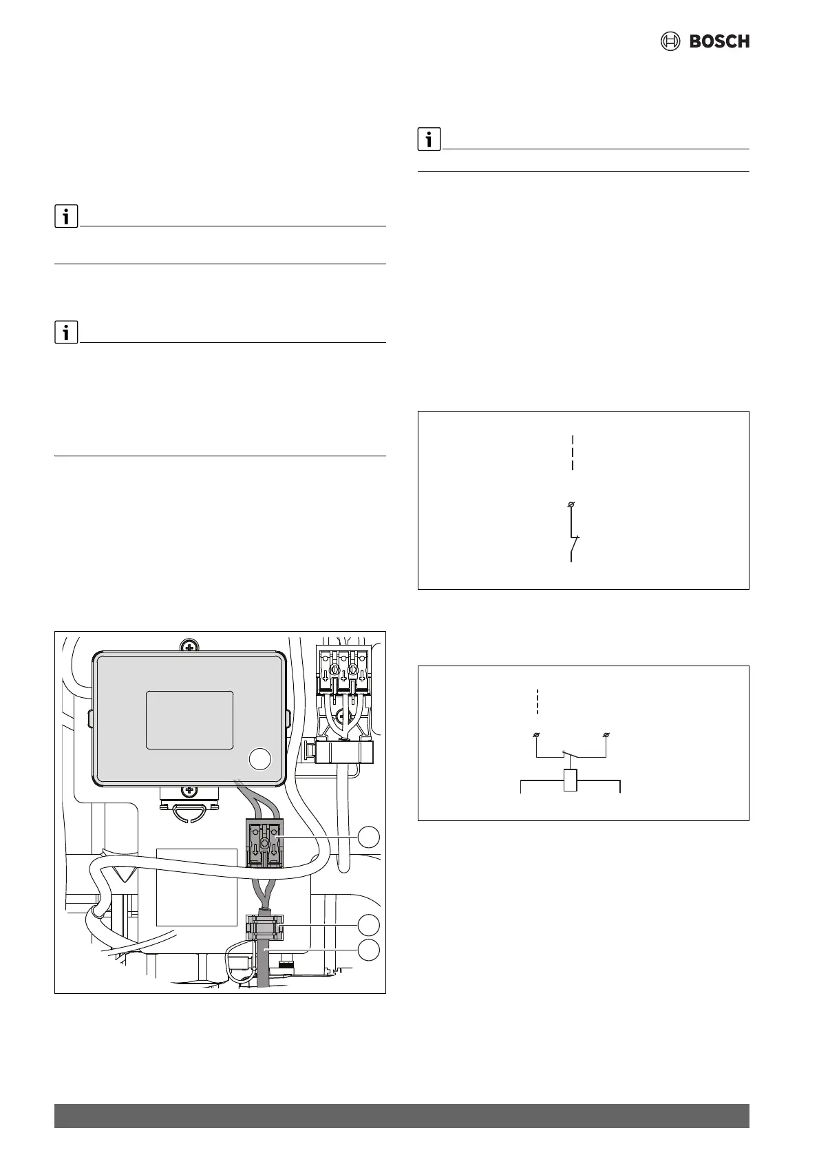
Fig. 33 Connection for external booster heater with 230 V alarm output
If the external booster heater is not equipped with a 230 V alarm output:
▶ Connect alarm signal as shown in Fig. 34 to the installer module at
terminal FM0 .
Fig. 34 Connection for external booster heater without 230 V alarm
output
0010030936-002
10V, 12V, 24V, 110V ...
64
FM0
61
 Loading...