28
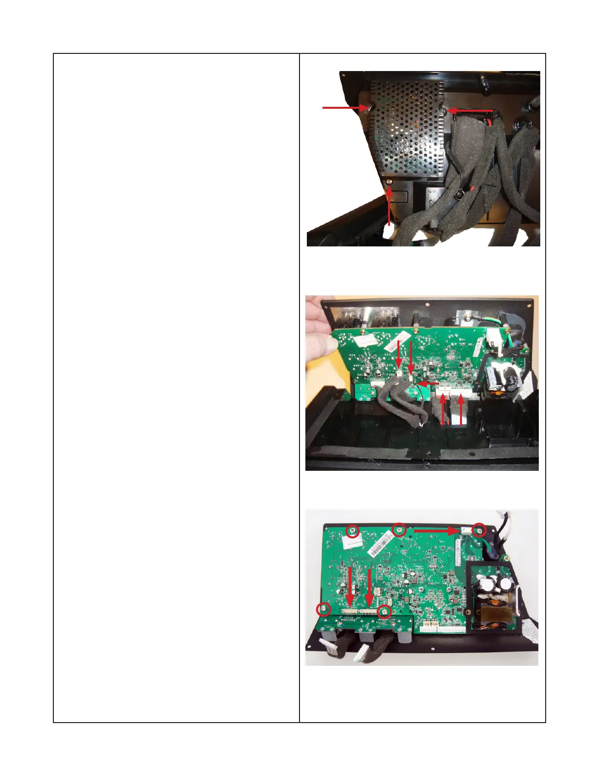
Figure 18
Figure 19
Figure 20
Disassembly Procedures
6. Removing the Main PCB and I/O panel
6.1 Remove the three screws indicated by the
arrows as shown in gure 18.
6.2 Lift the main PCB away from the enclosure to
expose the connectors as indicated by the arrows
shown in gure 19. Remove the connectors.
7. Removing the Main PCB from the I/O Panel
7.1 Remove the 5 screws indicated by circles
and the two control board connectors and power
connector indicated by arrows as shown in gure
20.
Note: The main PCB and the power switch board
are connected by a six pin connector. Figures 21
and 22 on page 29 show the connectors. There
will be a small amount of upward force required
with the main PCB to separate the main PCB
from the power switch board connector.
 Loading...