30
Disassembly Procedures
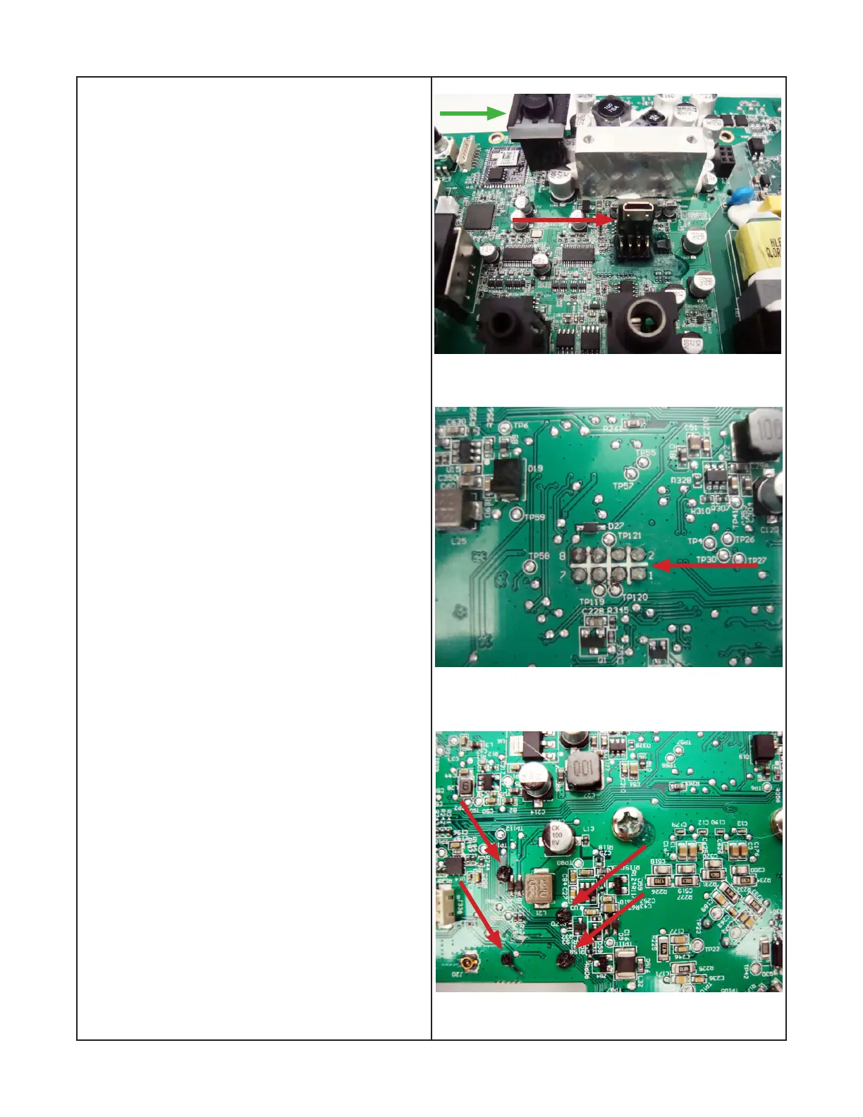
Figure 25
Figure 26
Figure 27
9. Bluetooth
®
button and micro USB
replacement.
9.1 Perform procedures 5 thru 7.
9.2 The arrows in gure 25 shows the Bluetooth
®
button and the Micro USB connector, both are
located on the Main PCB assy.
9.3 Figure 24 shows the main PCB and the eight
pins which need to be unsoldered to remove the
Micro USB.
9.4 Figure 27 shows the Bluetooth
®
button which
is heat staked as indicated at the arrows. Wire
cutters will be needed to remove the excess
plastic.
 Loading...