31
Disassembly Procedures
10.1 Power Switch and Power Switch PCB
Assy removal.
10.2 Perform procedures 5 thru 7.
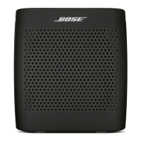
10.2 Figure 28 shows the insulator covering
the power switch connect PCB. The red arrow
indicates the section of the insulator that must be
peeled away to access the PCB.
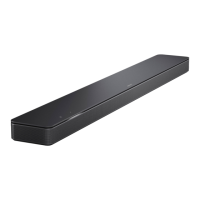
10.3 Remove the two screws indicated by arrows
in gure 29. Unsolder the three power switch
terminals from the power switch connect PCB as
indicated by the red circle and remove the power
switch connect PCB which also contains the
power LED.
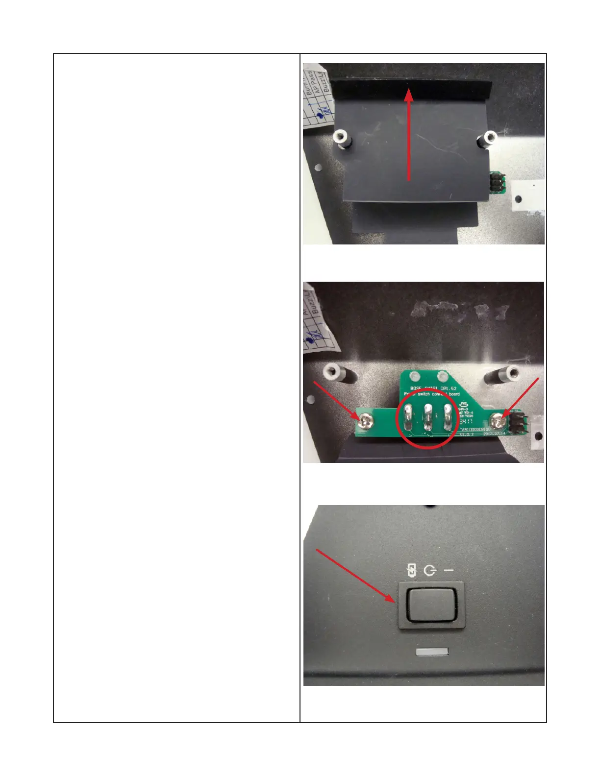
10.4 Figure 30 arrow indicates the power switch.
Remove the switch from the nished side of
the I/O panel indicated by the red arrow while
depressing locking tabs.
Figure 28
Figure 29
Figure 30
 Loading...