3. INSTALLATION
16KE-430D, BE-438D
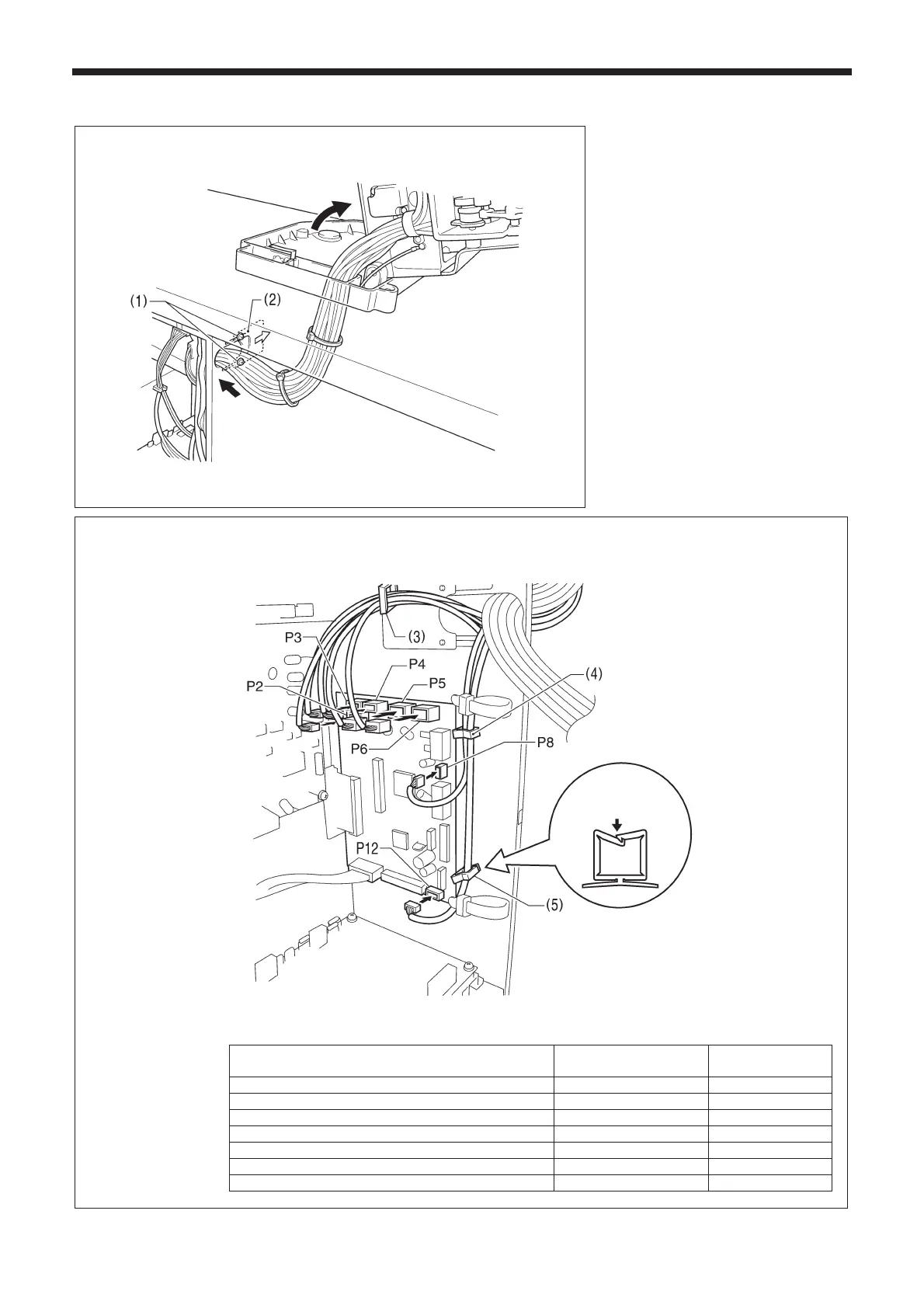
3-10. Connecting the cords
1. Gently tilt back the machine head.
2. Pass the cord bundle through the hole
in the work table.
3. Loosen the two screws (1), and then
open the cord presser plate (2) in the
direction of the white arrow and pass
the cord bundle through the opening.
4. Securely connect the connectors as
indicated in the table below.
Note:
• Check that the connector is facing
the correct way, and then insert it
firmly until it locks into place.
• Secure the cables with cable ties
and cord clamps, while being careful
not to pull on the connector.
< Main P. C. board >
Connectors
Connection location on
main P. C. board
Cord clamps
X pulse motor encoder [5-pin] White P2 (X-ENC) (3)
Y pulse motor encoder [5-pin] Blue P3 (Y-ENC) (3)
Work clamp encoder [5-pin] Black P4 (P-ENC) (3)
Foot switch [10-pin] P5 (FOOT) (3)
Operation panel [8-pin] P6 (PANEL) (3)
Machine head switch [3-pin] P8 (HEAD-SW) (4)
Thread clamp sensor [6-pin] P12 (TPK-SEN) (4), (5)
4413Q
Lock the cord
clamp securely.
4412Q
 Loading...