38
OPTIONAL BATTERY PACK OPERATION, Cont.
Optimum Battery Pack Performance, Cont.
3. If conditions permit, avoid charging and discharging the battery pack in extreme cold. Due to
the chemistry of batteries, low temperatures decrease the capacity of the battery pack
significantly causing a greater depth of discharge at colder temperatures than at room
temperature. The battery pack will function without problems at temperatures as low as 14 °F
(-10 °C) but will not last as many cycles as it would at room temperature.
4. Avoid storing the battery pack after discharging. If the battery pack is to be left for several days
or more, make certain that it is charged before storage. The optimum environment for batteries
is to charge while stored. The type of charger used in the indicator will not damage the
batteries in any way even if the battery pack is left charging indefinitely.
APPENDIX A – ANALOG OUTPUT OPTION (DAC) BOARD
This appendix describes the installation, setup and calibration of the optional Analog Output Option
DAC (Digital to Analog Converter) board. This option consists of both a 0 to 10 volt and 4 to 20
mA analog output.
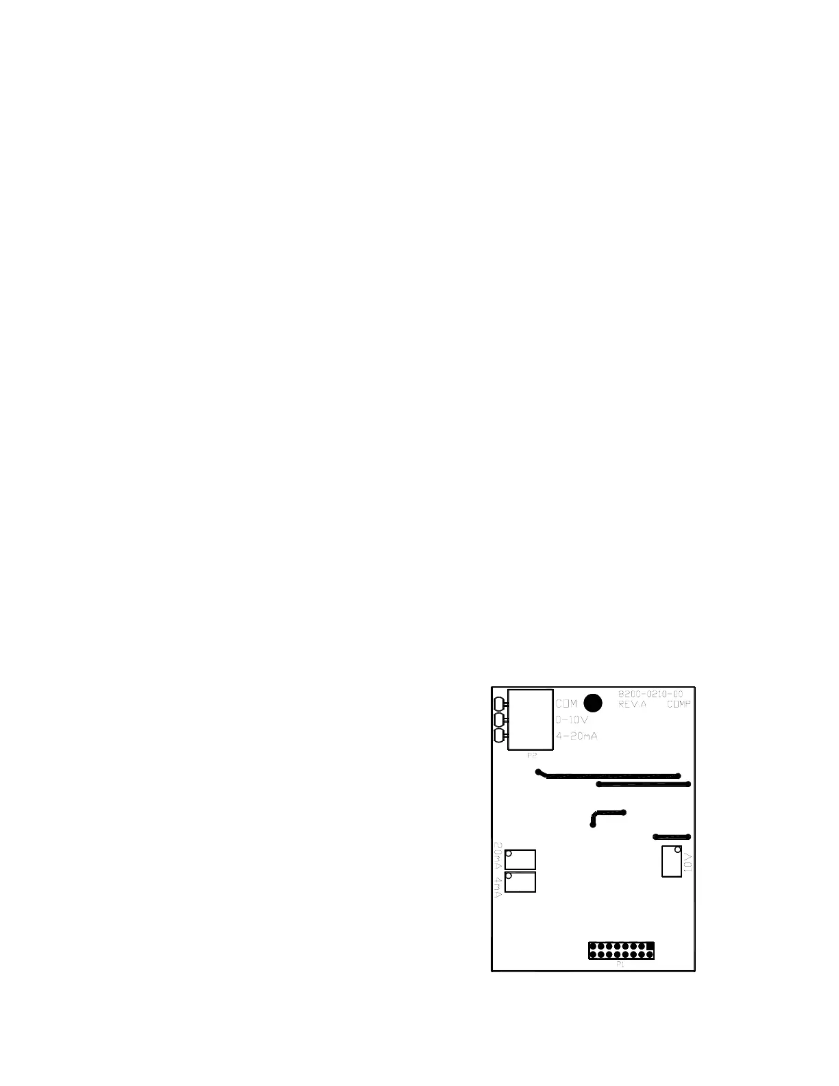
The Analog Output Option (DAC) board (Cardinal p/n 8200-C210-0A) is a 14-bit (16,383 states)
analog representation of the displayed weight. The maximum load resistance for the current
output is 500 ohms. The minimum load resistance for the voltage output is 2K ohms. Connections
are made via a terminal block on the back of the option board . Refer to Figure No. 15 for the
connector pin layout.
The 200 Series Indicators feature complete "ranging" for DAC output. Users may select a weight
range to be used for a selectable voltage range. This covers all current indicators/users and
expands the capabilities for new applications. The 200 Series Indicators also have auto-detect for
option board installation. When the DAC board is found, additional prompts will be added to
Setup. The main menu adds "dAC" (dAC?) after "LoCoUt", In addition, the calibration sequence
includes the steps necessary to calibrate the analog output.
INSTALLATION
Mounting the DAC Board
NOTE!
Should your indicator come with the DAC board already installed, the following information
describing the mounting of the board does not apply. Proceed to the Cable Installation section.
1. Make sure the power to the indicator is OFF. Unplug
the AC adapter and/or remove the battery.
2. Remove the twelve (12) screws securing the back
panel to the main housing.
3. Lift the back panel from the main housing, taking care
not to stretch the cable and wires between the panel
and main housing.
4. Locate the threaded mounting stud (below J2) and
connector P5 on the main board.
5. To install the DAC board, carefully align the DAC
board P1 (pins on trace side of DAC board) with
connector P5 on the main board.
6. Align the hole in the DAC board with the threaded
mounting stud (below J2) on the main board.
7. Apply even downward pressure to the end of the DAC
board with P1.
8. Using the lock washer and hex nut supplied with the
DAC board, secure the DAC board to the main board.
Figure No. 15 - DAC Board, Rear View

 Loading...